EC stands for extended capabilities and we've done just that.
|
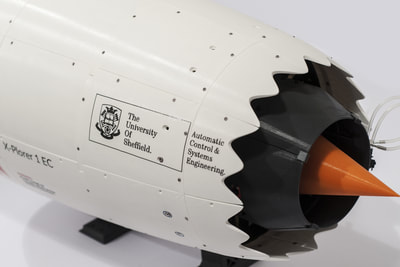
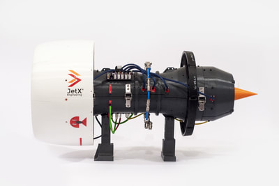
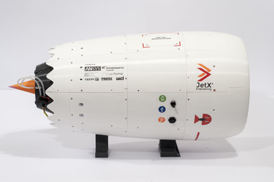
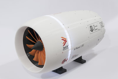
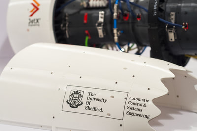
The second engine of the X-Plorer family builds upon the breakthrough of its predecessor, whilst being focused on control and actuation systems research. EC stands for extended capabilities and this projects marks the start of our collaboration with the University of Sheffield. It was commissioned in December 2017 followed by a brief redesigning period to address key issues and was delivered in October 2018.
Prototyping began on the 10th of April and was completed 164 days later, transforming a total of 670 parts from CAD to reality for main components, development parts and spares. Despite its near identical core to the XP1, on this page we would like to share some of the key improvements improving various aspects of the engine's performance and user experience. |
- 1300+ Total parts
- 666 Fasteners - 5.0:1 Bypass ratio - 269 3D-printed parts - High-bypass turbofan - 12 integrated sensors |
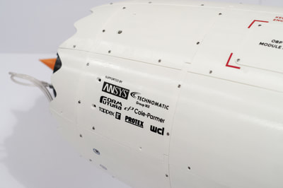
The X-Plorer 1 EC was kindly sponsored by
CORE DESIGN
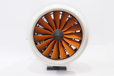
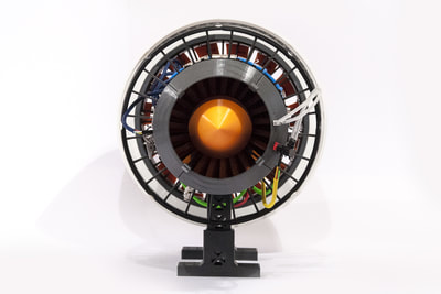
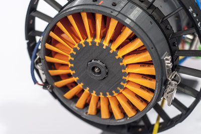
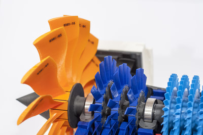
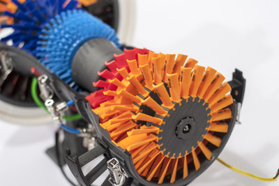
The EC includes a core that is almost identical to that of the X-Plorer 1 with two main differences; the updated fan blades and the shift of stage 2 of the turbine from the HP shaft to the LP shaft. The target for HP-to-LP rotational speed ratio for the X-Plorer family is between 2.5 and ~3. When the X-Plorer 1 first ran to a FAD of 190LPM, the actual ratio was measured to be ~13-15 which, needless to say, is significantly higher than the target. Testing in Sheffield in October 2018, showed that at a similar FAD, the ratio was brought down to ~3.5. To recap, here are some key information about the X-Plorer 1 EC:
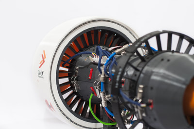
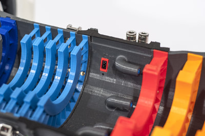
Ease of assembly and access to the core was one of the key areas of improvement between the XP1 and the EC. This was both to address a number of issues that came up during the assembly of the X-Plorer 1 in early 2017, as well as make the substitution of certain parts easier as this would be a more frequent requirement during testing and operation at the Rolls-Royce UTC on Control, Monitoring and Systems Engineering within the University of Sheffield. Using hundreds of Tappex heat-pressed inserts and six sets of PROTEX spring-loaded toggle latches were two of the main additions to the design that worked great with our 3D-printed assemblies!
- Axial flow turbofan
- 5.0:1 bypass ratio
- Double-spool
- 26.4 cm fan diameter
- 73.4 cm total length
- 8.1 kg gross weight
- 3 LPC stages, 5 HPC stages
- 3 LPT stages, 1 HPT stage
Ease of assembly and access to the core was one of the key areas of improvement between the XP1 and the EC. This was both to address a number of issues that came up during the assembly of the X-Plorer 1 in early 2017, as well as make the substitution of certain parts easier as this would be a more frequent requirement during testing and operation at the Rolls-Royce UTC on Control, Monitoring and Systems Engineering within the University of Sheffield. Using hundreds of Tappex heat-pressed inserts and six sets of PROTEX spring-loaded toggle latches were two of the main additions to the design that worked great with our 3D-printed assemblies!
EMS v2.0
Electronics
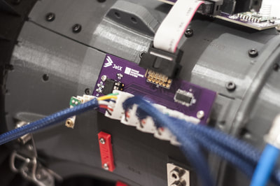
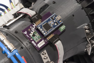
The development of the integrated electronics systems was one of the most challenging parts of making the X-Plorer 1. We learned a lot of things about the performance and reliability of the system, as well as the realistic conditions for some of the measured properties that can be expected from our models. Taking all these things in mind, resulted in a much improved version in many respects, the development of which was condensed to less than 9 months. Similar to the EMS of the X-Plorer 1, the updated system consists of:
- 2 ARM-based processors for data processing and transmission
- 2 Wireless transceivers
- 4 PCBs on the engine (3 on the core and 1 on the nacelle)
- 2 infrared RPM sensors
- 6 MEMS absolute pressure sensors
- 1 radial glass thermistor for bearing temperature monitoring
- 1 radial glass thermistor for battery safety monitoring
- 1 differential pressure sensor coupled to a Pitot tube for airspeed measurement
- 1 cantilever type vibration sensor
- 1 rechargeable Li-Ion battery for up to 2.5 hours of autonomous operation
- Fully integrated strip for system and power indications
Further to these and even though the PCBs have been designed exclusively by our team, this was the first time that we had them professionally made in the US! The boards had a much more neat and professional look, but were also easier to solder onto and assemble. In addition to the technical upgrades, a practical improvement came from embedding part of the new circuit on a nacelle panel, which also allowed for turning on/off and charging without ever having to take any part or hatch cover out, as this was the case previously.
Software Update
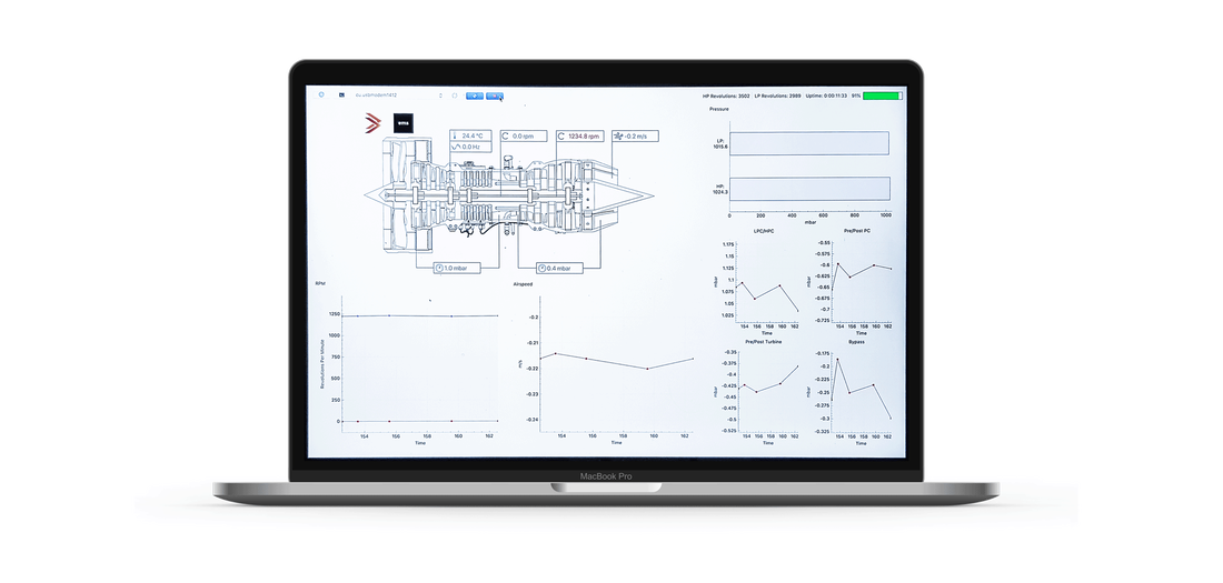
A number of improvements have been made on the software end. Our GUI was not just updated to reflect the system changes for the EC, but was re-designed for a much neater and practical look. By reducing the number of live charts, we concentrated all vital information in one, concise engine diagram which not only displays all information at-a-glance, but also shows more clear warning when critical values are reached.
The logging capabilities were also improved as far as the sampling intervals and export format are concerned. Lifetime counters have also been added for both shafts and a number of bugs and minor issues in the previous code have also been addressed.
The logging capabilities were also improved as far as the sampling intervals and export format are concerned. Lifetime counters have also been added for both shafts and a number of bugs and minor issues in the previous code have also been addressed.
FAN BLADES
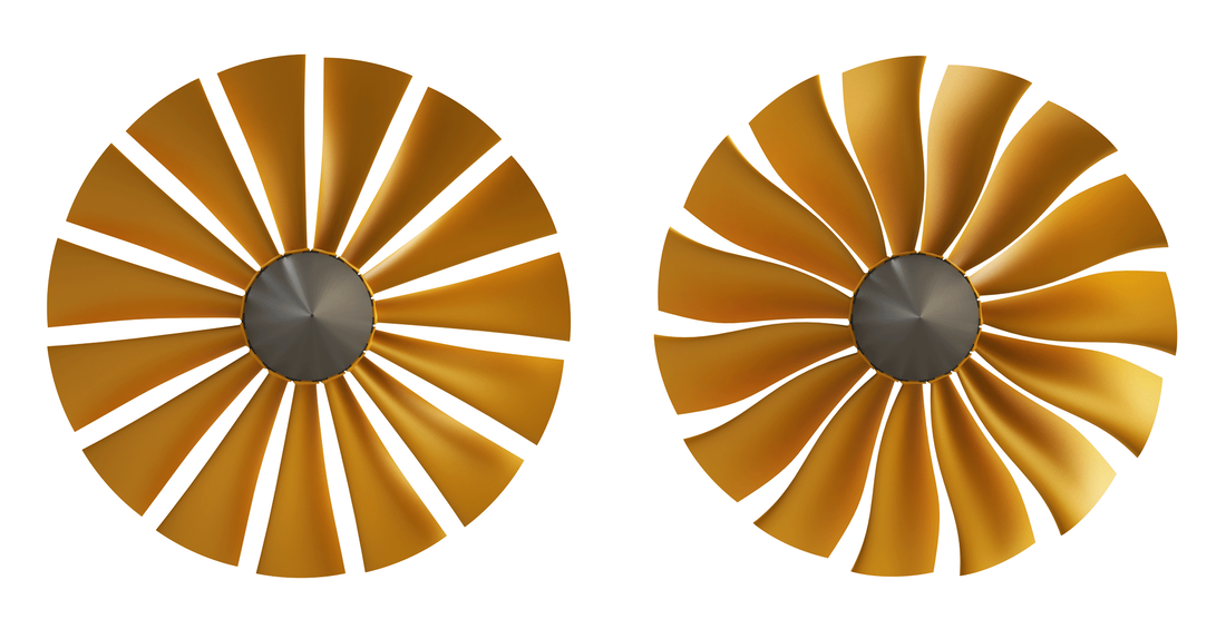
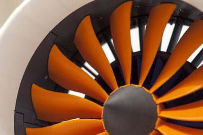
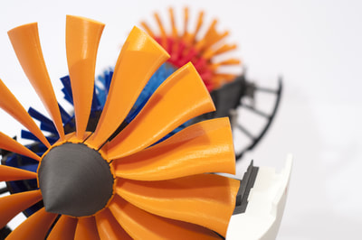
Our first generation fan blades followed a very strict design process dictated by the fundamental principles of aerofoil design. As a result, they looked more like the fan blades one would encounter in the early engines of the 60s and 70s. The clear room for improvement was exploited last year by the compressor team which delivered the second generation of fan blades used in the EC.
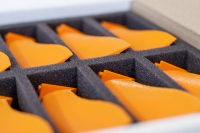
A new design was proposed to reduce drag and the overall perturbation of the flow. This used NACA5510 as the starting point with modifications to the pitch and twist angles, before being computationally evaluated. The resulting blade from this study offered an increase in mass flow rate from 1.7 kg/s to 2.3 kg/s as well as a 30.8% increase in the maximum theoretical thrust.
A new design was proposed to reduce drag and the overall perturbation of the flow. This used NACA5510 as the starting point with modifications to the pitch and twist angles, before being computationally evaluated. The resulting blade from this study offered an increase in mass flow rate from 1.7 kg/s to 2.3 kg/s as well as a 30.8% increase in the maximum theoretical thrust.
PART MARKING
|
Logging and traceability have always been taken into consideration. Since we got our first 3D printer, we established a serial numbering system that keeps tracks of several prototyping parameters; from the material to the printing speed and any post-processing carried out. Out of the 1190+ parts we have ever produced, only 533 are actually on an engine at one time. However, the ink from pen markings often leaked along the layers and faded, making it very difficult to identify the serial number.
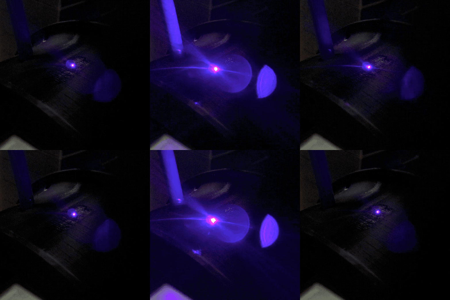
A low-cost laser marking procedure has been implemented and was used for a large proportion of the EC parts. A layer of powder, consisting of graphite and clay, is locally applied prior to marking and is later washed off. It is a time-consuming process but produces markings with significantly improved quality and durability. |
FREE AIR DELIVERY
Going forward, we are looking to push our engines to their limits and collect a wide range of data at higher speeds. Assuming access to a compressor with high Free Air Delivery (FAD) is provided, it was necessary to modify the Pneumatics Control Unit (PCU) to be capable of handling such flow rates. In the process, we also reviewed some of the components in the first PCU, whilst taking design limitations on the engine side into account.
The main design limitation concerned the use of tubing with 4mm ID on the propulsion chamber. On one side, this is a bottleneck for high flow rates under relatively low pressures and on the other hand, using tubing with 6mm ID would be impractical due to the minimum bend radius. The use of a single control valve, a twin 4mm ID tube from the PCU to the engine and the provision for 2 280LPM flow meters allow us to release up to 500LPM!
Thanks to the huge help and expertise of the Technomatic Group, we were able to both use new components and customise our PCU to better suit those needs. Following our tests in October 2018 both on the X-Plorer 1 and the X-Plorer 1 EC we have also launched a review of the nozzle ring and way of managing the flow distribution more efficiently. Back in Glasgow we already have an experimental setup and components for a number of arrangements, which will be tested and optimised in the near future.
3D PRINTING
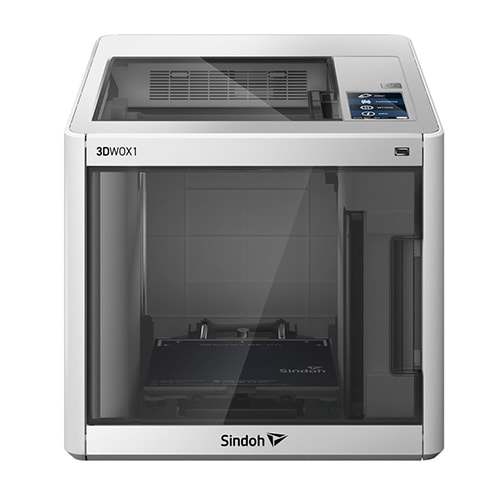
As before, 3D printing is the main manufacturing method for our engines due to the tremendous value for a large number of unique parts. The EC is probably the last of our engines to only consist of FFF-produced parts, as we anticipate to add SLA to our in-house capabilities by the start of 2019. The EC is also printed exclusively using Formfutura filaments, mostly EasyFil PLA and, our favourite ABS-based filament, TitanX!
This time, the shorted print lasted for just 10 minutes, prototyping part of the housing for the EMS receiver. The main part of the PCU casing took 46 hours and 39 minutes non-stop to complete, consuming 81m of filament in the making. Even though a time saving of over 10 hours was achieved through a design change, the PCU casing remains the most time-consuming part to print. The average print time per part or batch for the EC was 7 hours 35 minutes and 20 seconds!
This time, the shorted print lasted for just 10 minutes, prototyping part of the housing for the EMS receiver. The main part of the PCU casing took 46 hours and 39 minutes non-stop to complete, consuming 81m of filament in the making. Even though a time saving of over 10 hours was achieved through a design change, the PCU casing remains the most time-consuming part to print. The average print time per part or batch for the EC was 7 hours 35 minutes and 20 seconds!
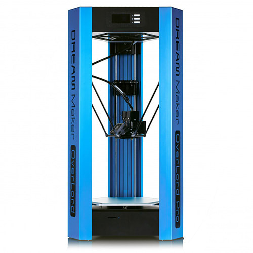
Printers Used
Stats
Development, testing & production of the X-Plorer 1 EC
|
parts |
hours of printing |
meters of plastic used |


