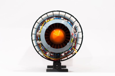
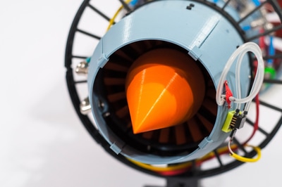
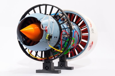
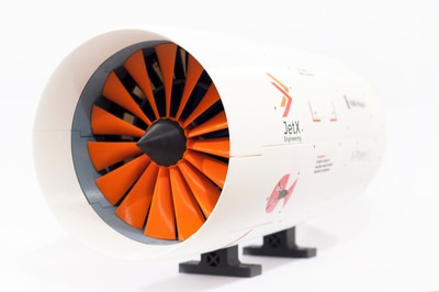
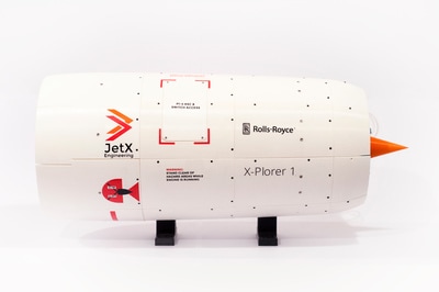
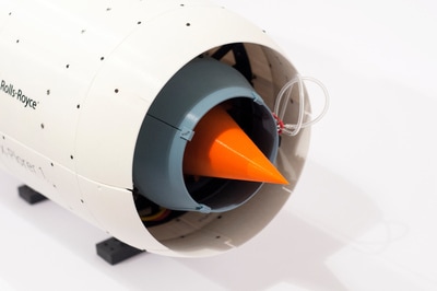
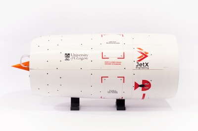
The award-winning model that redefined aerospace education.
|
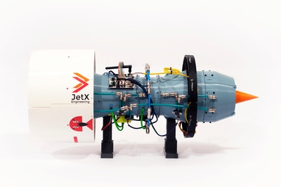
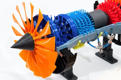
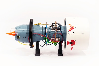
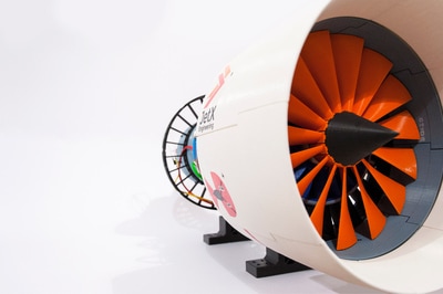
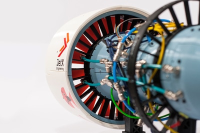
The first JetX engine of the X-Plorer family is here to change everything in aerospace education. The X-Plorer 1 entered development in late 2014 and stage 1 optimisation was completed in August 2016. 40 young engineers worked hard in various stages of the development of subsystems from pneumatics to electronics.
Prototyping began in October 2016, following the completion of the testing phase which brought 150 parts from design to reality. 3D printing all the necessary parts will required over 2900 printing hours and almost 5km of filament! |
- 800+ Total parts
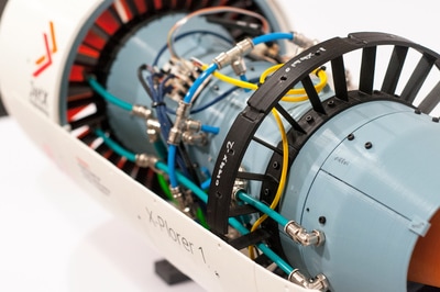
- 308 Fasteners - 5.0:1 Bypass ratio - 260 3D-printed parts - High-bypass turbofan - 10 integrated sensors |
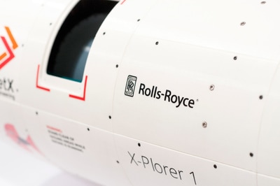
The X-Plorer 1 was kindly sponsored by
DESIGN
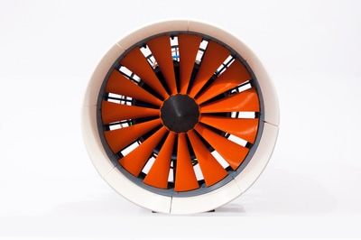
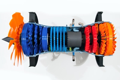
The design is one of the lengthiest stages of the project as this involves intensive theoretical and modelling work. In industry, the thrust requirement is one of the first things defined for the design team. After it was decided that our first ever engine would be a high-bypass turbofan, the bypass ratio of 5.0:1 was defined and an advisory limitation for the maximum core diameter was set. This was to allow for practical manufacture given the building capacity of our 3D-printer, but the design teams were allowed to exceed that if necessary. Based on three specifications, a theoretical model for an engine of this size and capacity was constructed, primarily for the compressor, turbine and exhaust sections. Often these models assumed combustion taking place, later attempting to exclude this effect to predict the behaviour of the prototype. Some of the specifications of the X-Plorer 1 are:
These models generated a number of values that defined features in our design such as the geometry of the rotors, stators, fan blades, etc. All 3D models were designed in Solidworks, which was also used to construct the visual assemblies.
- Axial flow turbofan
- 5.0:1 bypass ratio
- Double-spool
- 26.15cm fan diameter
- 72cm total length
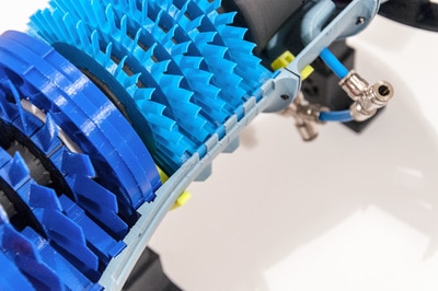
- 3 LPC stages, 5 HPC stages
These models generated a number of values that defined features in our design such as the geometry of the rotors, stators, fan blades, etc. All 3D models were designed in Solidworks, which was also used to construct the visual assemblies.
Electronics
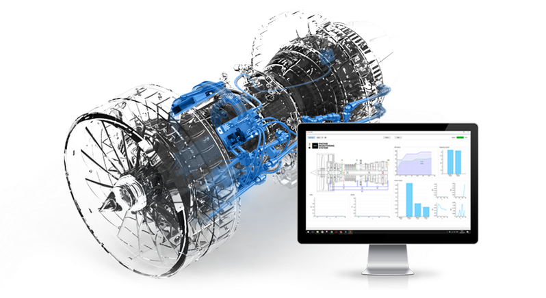
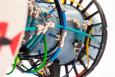
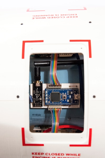
The design of the electronics system was also done in parallel with the core design both because it had to fit and work around the rest of the engine, as well as due to the fact that edits were required on other parts to accommodate electronics. From the design of the traces for the Printed Circuit Boards (PCBs) to the software and user interface, the Engine Monitoring System (EMS) was developed by us. The EMS consists of:
ANALYSIS
The first step in optimising the design is to perform computational analyses to investigate the how the flow changes throughout the engine, as well as the effect that specific forces and loading conditions have on the parts. When several designs are available for one part, CFD analyses are performed with tools that include Solidworks Flow Simulation, ANSYS Fluent & Star CCM+ on single stators, rotors or multi-stage segments to assess which one performs the best.
Finite Element Analyses are performed to identify high stress concentrations and assess whether failure is likely under different loading conditions. Centrifugal forces can be significant even on a model of this size and failure scenarios are also modelled to assess whether an impact would be contained. Our team is working to develop more advanced models that are able to simulate the complex behaviour of additively-manufactured parts.
Finite Element Analyses are performed to identify high stress concentrations and assess whether failure is likely under different loading conditions. Centrifugal forces can be significant even on a model of this size and failure scenarios are also modelled to assess whether an impact would be contained. Our team is working to develop more advanced models that are able to simulate the complex behaviour of additively-manufactured parts.
3D PRINTING
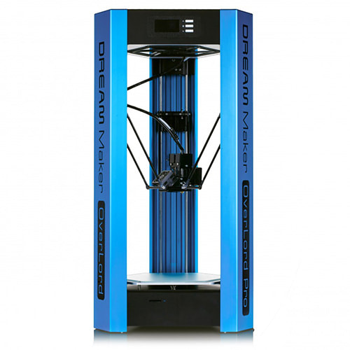
3D printing is an integral part of our projects and we use the technology extensively! We operate a DreamMaker OverLord Pro, often at full capacity and to date we've used PLA, ABS, nylon, PETG and more for tests. FFF was the only 3D printing technology used for the X-Plorer 1 and throughout the year-long testing phase, we managed to optimise the process for the printer and plastic used to achieve a major increase in success rates.
The shorted print lasted for just 7 minutes, prototyping both brackets for securing the temperature sensors in their position. The main part of the PCU casing took 58 hours and 30 minutes non-stop to complete, consuming 105m of filament in the making. Loose tolerances can be a major issue in engineering assemblies, which is why testing and altering the design for the process is essential.
The shorted print lasted for just 7 minutes, prototyping both brackets for securing the temperature sensors in their position. The main part of the PCU casing took 58 hours and 30 minutes non-stop to complete, consuming 105m of filament in the making. Loose tolerances can be a major issue in engineering assemblies, which is why testing and altering the design for the process is essential.
Printers Used
Stats
Development, testing & production of the X-Plorer 1
|
parts |
hours of printing |
meters of plastic used |


