
Back to Aeolus directory
5. Turbines
5.1 Principles of Operation
5.2 Energy Transfer
5.3 Design & Manufacture
5.4 Materials
5.1 Principles of Operation
The primary function of a turbine is to provide the power required by the compressor and the engine auxiliary systems for their operation. Even in engines where the exhaust gases are not the primary propulsion means (i.e. in turboprops), turbines are still used to provide the power that drives the propeller(s). This is achieved by gradually expanding the hot and pressurised gases from the combustion chamber. In efficient turbines, the blade tips can travel with velocities up to 390 m/s (1280 ft/s).
To generate the required driving torque in the most efficient manner, multiple stages are employed, each consisting of a row of stationary guide vanes and a row of rotors. The number of stages depends on the:
From these, it becomes apparent that engines with high/very high compression ratios require turbines with more stages as well. The number of spools depends on the compression and bypass ratios, as well as the manufacturer, but for essentially all commercial engines it will be 2 or 3. In very high bypass ratios, it is rather efficient to use 3 spools with the middle one being commonly branded the intermediate-pressure (IP) shaft. In cases where a turboprop or helicopter shaft is driven, a free-power turbine might be used. In both these cases and in the presence of a typical axial compressor arrangement, the turbine shaft driving the propellers can be mechanically independent of the shaft driving the compressor.
To generate the required driving torque in the most efficient manner, multiple stages are employed, each consisting of a row of stationary guide vanes and a row of rotors. The number of stages depends on the:
- Number of spools/shafts of the engine
- Required power reduction before the gases enter the exhaust
- Required rotational speeds
- Design and manufacturing limitations of the turbine size
From these, it becomes apparent that engines with high/very high compression ratios require turbines with more stages as well. The number of spools depends on the compression and bypass ratios, as well as the manufacturer, but for essentially all commercial engines it will be 2 or 3. In very high bypass ratios, it is rather efficient to use 3 spools with the middle one being commonly branded the intermediate-pressure (IP) shaft. In cases where a turboprop or helicopter shaft is driven, a free-power turbine might be used. In both these cases and in the presence of a typical axial compressor arrangement, the turbine shaft driving the propellers can be mechanically independent of the shaft driving the compressor.
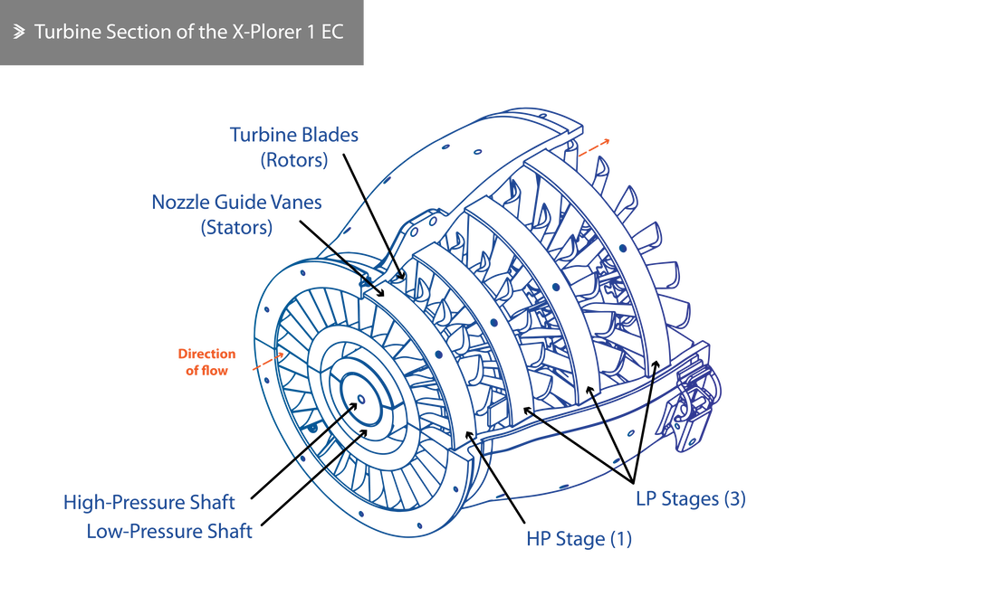
The mean velocity of a turbine blade plays a very important role in defining the maximum possible efficiency of each stage. This is because the pressure drop that occurs is proportional to the square of the blade velocity. However, the faster the rotation of the turbine, the higher the stresses in its disk requiring larger and subsequently heavier components. Ultimately, the design of a turbine as a whole is driven by the need to balance the desired power requirement and its weight. The use of two spools allows for a slightly smaller turbine to be used for the same power requirement, where each spool operates closer to its optimal velocity.
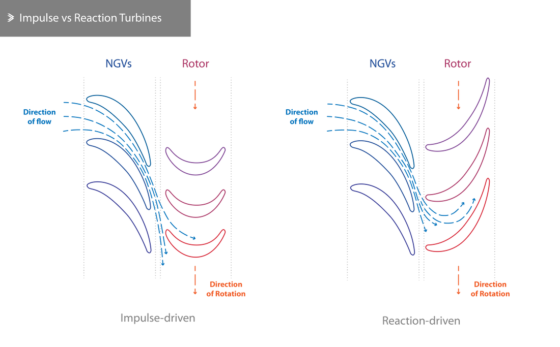
Both in our projects and in industry, the design of the turbine vanes and rotors is based on calculations around the aerodynamic performance of different designs. Both have aerofoil cross-sections but their design can vary noticeably. The arrangement of the aerofoils is such that causes an impulse which drives the rotors. The overall process may be aided by the acceleration of the flow as it leaves the vanes. To summarise, in an impulse turbine, the overall pressure drop per stage occurs in the stationary vanes and the rotors experience an impulse from the gas flow. In a reaction turbine, the overall pressure drop occurs in the space between rotor blades, as they converge towards their trailing edge. Where both principles are applicable, their contribution to the power generation is approximately evenly split.
Both in our projects and in industry, the design of the turbine vanes and rotors is based on calculations around the aerodynamic performance of different designs. Both have aerofoil cross-sections but their design can vary noticeably. The arrangement of the aerofoils is such that causes an impulse which drives the rotors. The overall process may be aided by the acceleration of the flow as it leaves the vanes. To summarise, in an impulse turbine, the overall pressure drop per stage occurs in the stationary vanes and the rotors experience an impulse from the gas flow. In a reaction turbine, the overall pressure drop occurs in the space between rotor blades, as they converge towards their trailing edge. Where both principles are applicable, their contribution to the power generation is approximately evenly split.
5.2 Energy Transfer
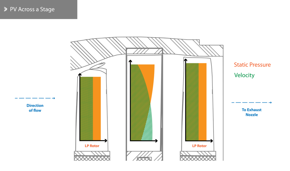
The operation of the turbine is inherently linked to the constant transfer of energy from the hot combustion gases and the rotors that ultimately drive the compressor, fan and auxiliaries. This transfer is never carried out with 100% efficiency due to both mechanical and thermal losses, but 90% is a reasonable assumption in most cases. Upon leaving the combustion chamber, the gasses are travelling at sonic speeds which, given their temperature, are around double the sonic speed at room temperature. When the flow eventually hits the turbine blades, energy is transferred as the rotor is accelerated to high rotational velocities. The driving torque of the turbine depends on the flow rate of the gases and the change in energy between the input and output stages. If the energy transfer is relatively efficient/high, then the flow at the output of the turbine should be steady and relatively laminar. High turbulence at the output indicates low efficiency and subsequently leads to lower efficiency in the exhaust section, as well as to vibrations that can be structurally damaging for the rear of the engine.
Both the nozzle guide vanes and the rotor blades are designed to feature a twist from the root to the tip. In other words, their angle of attack is higher at the tips than at their roots. The purpose of this is to evenly distribute the work done by each section of the blade and adjust the axial velocity of the flow as this exits the stage.
Both the nozzle guide vanes and the rotor blades are designed to feature a twist from the root to the tip. In other words, their angle of attack is higher at the tips than at their roots. The purpose of this is to evenly distribute the work done by each section of the blade and adjust the axial velocity of the flow as this exits the stage.
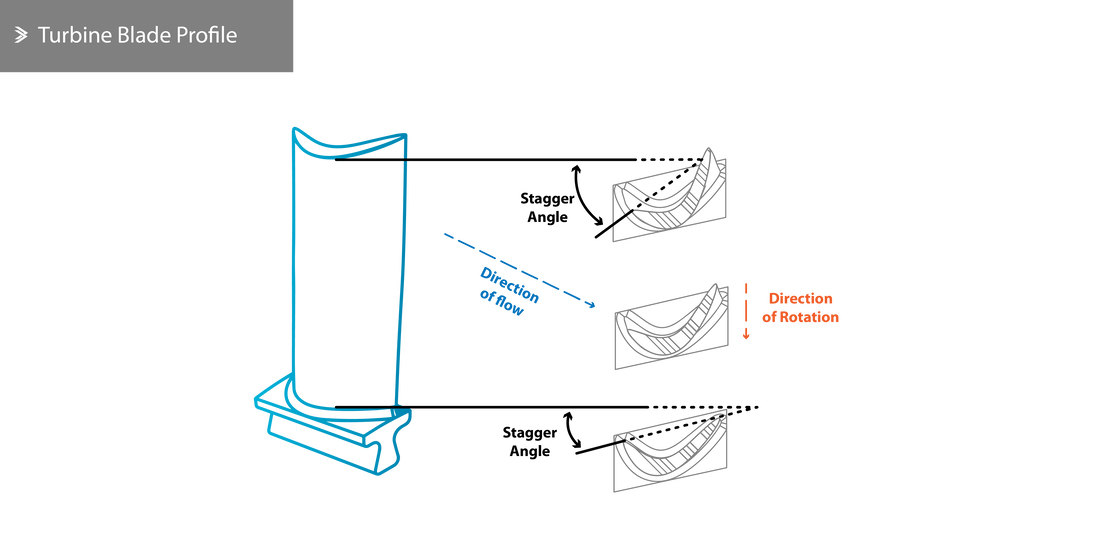
This geometry also induces changes in the velocity, pressure and temperature of the gases along the length of the blade. The degree of reaction also varies; at its lowest at the blade root and at its highest at the blade tip. As mentioned previously, there are a few reasons why the efficiency of a turbine can never be 100%. A 90s-made triple-spool turbofan used as an example would suffer from 3.5% of aerodynamic losses at the rotors and 4.5% of aerodynamic losses in the vanes and around the rotors (bleed).
5.3 Design & Manufacture
From a manufacturing point of view, the turbine can be broadly divided into the combustion chamber nozzles, the subsequent nozzle guide vanes, the turbine disks and the rotor blades. The shaft(s) connecting the turbine disks to the compressor and the fan can be assembled from multiple segments or made as a single component (in some cases roll-formed to avoid seams i.e. from welds).
Nozzle Guide Vanes
The NGVs consist of aerofoils with a converging path between neighbouring aerofoils and are mounted on the turbine casing in such a way that allows for thermal expansion. They may be manufactured as an individual part or segments with 3-8 aerofoils and, in almost all cases, feature a hollow core, or more complex air distribution channels, for cooling.
Disks
Turbine disks are manufactured from castings/forgings with either a partial shaft or a spline for connecting to the main shaft. At the perimeter of the disk, slots for the blade roots are milled, even though blades can also be permanently fixated via linear friction welding, forming a 'blisk'.
Cooling currents are required from both sides of the disks, mostly to counteract the effects of conduction from the hot blades.
Cooling currents are required from both sides of the disks, mostly to counteract the effects of conduction from the hot blades.
Blades
The blades are also aerofoil-shaped even though their design is less standardised than the profiles used for aircraft wings. The goal is to create a passage between blades that allows for a steady acceleration of the flow up to the narrowest point where the desired degree of reaction has been achieved.
The effective cross-sectional area depends on the mechanical and thermal properties of the material used, as well as the size of the cooling channels. For high operational efficiency, the thickness of the blades should be minimised but the final design is a compromise that eliminates the risk of cracking due to the thermal loading and unloading.
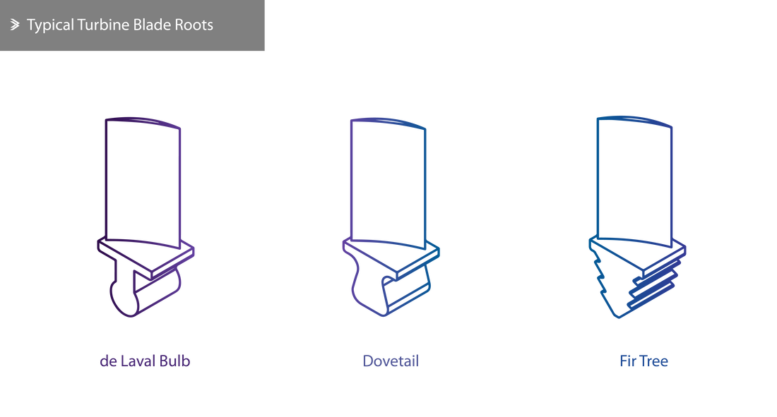
The attachment method of the blades to the disk is even more important in this case as the stresses that develop due to the tangential and centrifugal forces are effectively a key limitation to the top rotational velocity. In much older jet engines, turbine blades were secured using a de Laval bulb root. In more recent designs, dovetail roots and fir trees are more commonly used. Fir trees deliver a much-improved contact area against centrifugal forces but require high machining tolerance to make sure that all faces are exposed to roughly the same loading. When idle, the fit of the blades may appear somewhat loose but the clearances are designed so that the blades fixate themselves whilst in operation.
The effective cross-sectional area depends on the mechanical and thermal properties of the material used, as well as the size of the cooling channels. For high operational efficiency, the thickness of the blades should be minimised but the final design is a compromise that eliminates the risk of cracking due to the thermal loading and unloading.
The attachment method of the blades to the disk is even more important in this case as the stresses that develop due to the tangential and centrifugal forces are effectively a key limitation to the top rotational velocity. In much older jet engines, turbine blades were secured using a de Laval bulb root. In more recent designs, dovetail roots and fir trees are more commonly used. Fir trees deliver a much-improved contact area against centrifugal forces but require high machining tolerance to make sure that all faces are exposed to roughly the same loading. When idle, the fit of the blades may appear somewhat loose but the clearances are designed so that the blades fixate themselves whilst in operation.
To minimise losses due to air leaking between the blade tips and the casing, shrouds are often used. Each blade is manufactured with a small segment at its blade tip and when assembled they form a continuous ring. Finally, it is worth reminding that a jet engine turbine can never be designed in isolation. It must follow the requirements of its compressor very closely in order to operate efficiently across a range of conditions whilst avoiding surging or choking the compressor (the former from allowing revolution at very low speeds and the latter from allowing revolutions at very high speeds).
5.4 Materials
There are few environments that are more challenging for materials than the turbine. The exposure to very high temperatures is now coupled with huge mechanical requirements that arise from the high rotational speeds. It is absolutely necessary to lower the temperature that all turbine components are exposed to, to avoid creep.
Creep is a material's ability to slowly, but permanently, deform under a constant load that, if applied instantaneously, would not have caused any damage. Even though high temperatures are not a prerequisite for creep to occur, their presence accelerates this mechanism. In these conditions creep will inevitably occur but some materials take significantly longer to reach the end of operational life stage.
To put the loading requirements in context; a blade weighing around 75 grams is capable of exerting a pulling force to a disk rotating at max speed of over 2 tonnes! The stiffness of the material used should also be such that offer sufficient resistance to the bending loads of the large, fast-moving masses of air. Excellent fatigue and thermal properties are also desired, as well as very good corrosion resistance, which is, in fact, an issue with many modern jet engines. In this torturous material selection case, it is also worth remembering that the chosen material should be able to be formed with a conventional, or at least commercially practical, technique.
For any given material and acceptable part life, there is a maximum tolerable gas temperature and a maximum deliverable power rating. Early disks were manufactured from steel and other austenitic alloys, but even from that stage, it was apparent that no material would be suitable without internal cooling, which became more advanced over the years. Nowadays, most turbine components are manufactured from nickel alloys which offer excellent thermal, creep and fatigue properties at the cost of its density which is almost double that of titanium alloys.
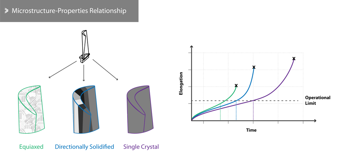
Materials research is a very active domain within aerospace. As far as turbine blades are concerned, one of the most innovative examples of microstructure control is that of the single-crystal blades. As-supplied plates of metals consist of multiple grains. In high-performance alloys, the grains may be 2-20μm wide but there is a vast range of options from alloying elements to melting and cooling routines that will yield significantly different microstructures. It is possible to 'grow out' a single crystal in a blade cast with superior mechanical properties and it is a method currently being used in industry.
Creep is a material's ability to slowly, but permanently, deform under a constant load that, if applied instantaneously, would not have caused any damage. Even though high temperatures are not a prerequisite for creep to occur, their presence accelerates this mechanism. In these conditions creep will inevitably occur but some materials take significantly longer to reach the end of operational life stage.
To put the loading requirements in context; a blade weighing around 75 grams is capable of exerting a pulling force to a disk rotating at max speed of over 2 tonnes! The stiffness of the material used should also be such that offer sufficient resistance to the bending loads of the large, fast-moving masses of air. Excellent fatigue and thermal properties are also desired, as well as very good corrosion resistance, which is, in fact, an issue with many modern jet engines. In this torturous material selection case, it is also worth remembering that the chosen material should be able to be formed with a conventional, or at least commercially practical, technique.
For any given material and acceptable part life, there is a maximum tolerable gas temperature and a maximum deliverable power rating. Early disks were manufactured from steel and other austenitic alloys, but even from that stage, it was apparent that no material would be suitable without internal cooling, which became more advanced over the years. Nowadays, most turbine components are manufactured from nickel alloys which offer excellent thermal, creep and fatigue properties at the cost of its density which is almost double that of titanium alloys.
Materials research is a very active domain within aerospace. As far as turbine blades are concerned, one of the most innovative examples of microstructure control is that of the single-crystal blades. As-supplied plates of metals consist of multiple grains. In high-performance alloys, the grains may be 2-20μm wide but there is a vast range of options from alloying elements to melting and cooling routines that will yield significantly different microstructures. It is possible to 'grow out' a single crystal in a blade cast with superior mechanical properties and it is a method currently being used in industry.
Back to Aeolus directory |
Next up: 6. Exhaust |

|