
Back to Aeolus directory
1. Introduction
1.1 Foreword
1.2 History
1.3 Propulsion Principles
1.4 Producing Thrust
1.5 Jet Engine Types
1.6 Jet Engine Design
1.7 Materials
1.1 Foreword
Jet engines are used on aircraft to provide thrust either directly, by producing a high-speed exhaust flow (jet), or by rotating a propeller.
Taking their output into account, jet engines can be generally characterised by their low weight and volume, as well as demanding performance requirements in a wide range of atmospheric pressure and temperature conditions. The jet engine is not only exposed to some of the most challenging operating environments but should also provide sufficient reliability, given its crucial role in an aircraft's operation.
The development of the jet engine over the last 50 years has been dramatic. In the early days of propulsion, the low speeds of the first aircraft and the inability of piston-driven engines to provide such thrust that would later power commercial airliners were two interlinked, yet fundamental issues.
1.2 History
Even though the jet engine in its current form is a relatively new invention, the principle that it is based on has been known for thousands of years. The first recorded jet mechanism was invented by the ancient Greek mathematician, Hero of Alexandria, around the 1st century AD, even though the first device probably dates back to the 2nd century BC.
The device constructed by Hero, the aeolipile, consists of a sealed container full of water and a sphere that is free to rotate and has two nozzles facing towards opposite directions attached to it. Heating the water in the main container produced steam which was routed to the sphere and upon exiting through the nozzles caused the rotation of the sphere. It is said that Hero manufactured the aeolipile after Egyptian priests asked for a device that would impress people when they opened the doors to the temples.
The device constructed by Hero, the aeolipile, consists of a sealed container full of water and a sphere that is free to rotate and has two nozzles facing towards opposite directions attached to it. Heating the water in the main container produced steam which was routed to the sphere and upon exiting through the nozzles caused the rotation of the sphere. It is said that Hero manufactured the aeolipile after Egyptian priests asked for a device that would impress people when they opened the doors to the temples.
During the 17th century, Isaac Newton established the laws of motion for bodies. As is widely known, the third law states that 'for every action, there must be an equal and opposite reaction'. To explain this principle, Newton came up with the example of a carriage equipped with a heated water container and a rear-facing nozzle which upon releasing the steam, would push the carriage forward. Even though this was never made, the principle is shared with modern aircraft.
In 1629, almost 50 years after Newton theoretically explained reaction forces, Italian engineer Giovanni Branca constructed the first steam turbine. He directed a nozzle onto a wheel with flat vanes causing it to rotate. Even though he never applied the technology in another context, he suggested that it could be used to power grinding and crushing machines, or even a sawing machine.
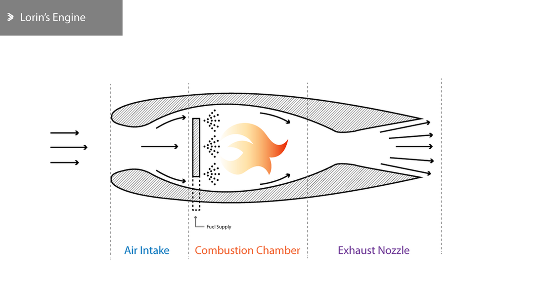
French engineer René Lorin patented a jet engine design in 1913 which was effectively a ramjet that was impossible to manufacture at the time.
In 1629, almost 50 years after Newton theoretically explained reaction forces, Italian engineer Giovanni Branca constructed the first steam turbine. He directed a nozzle onto a wheel with flat vanes causing it to rotate. Even though he never applied the technology in another context, he suggested that it could be used to power grinding and crushing machines, or even a sawing machine.
French engineer René Lorin patented a jet engine design in 1913 which was effectively a ramjet that was impossible to manufacture at the time.
A.A. Griffith was the first to theoretically set out and further investigate why newer jet engine designs failed to meet expectations. In 1926, he published work on an axial flow jet engine that consisted of a compressor that featured multiple stages and aerofoil-shaped blades, suggesting dramatic performance improvement. His design was considered rather complex but was eventually manufactured by Armstrong Siddeley Motors.
In 1930 Sir Frank Whittle invented the first turbojet for use in aircraft propulsion. Many other engineers and companies were attempting to deliver the first operational turbojet that would offer better specific fuel consumption than the piston-driven engines available at the time. This resulted in overly complex designs that were not technologically feasible. His first engine featured a centrifugal compressor, combustion chamber and a single-stage turbine, aiming to deliver a 4:1 compression ratio and at least 3,000hp. In 1936 he co-founded Power Jets Ltd and the prototype engine was manufactured by British Thomson-Houston leading to a successful test.
In 1939 the British government tasked Power Jets with the manufacture of an engine that would power a test aircraft by Gloster Aircraft. The W1 engine was manufactured and successfully tested in flight in 1941. This led to the development of the improved W2B for the Meteor aircraft.
German engineer, Hans von Ohain was working on a very similar engine at the same time as Whittle. The first successful flight using the He-3B engine on the Heinkel-produced He-178 aircraft took place in 1936 providing 880-1,100lbs of thrust. This run led to both BMW and Junkers Jumo getting involved in the axial flow jet engine manufacturing. The Me 262 was the first jet-powered fighter aircraft used by Germany during the war.
It wasn't until 1941 that notable progress on jet propulsion for aircraft was made in the US. Close cooperation with Power Jets and the British government led to Whittle's first engine being used by General Electric for research and development. Working with Bell Aircraft, GE delivered the CE-1A engine for the XP-59 aircraft in 1942.
By 1950, axial flow compressors with variable stator vanes emerged, along with double-spool engines offering major improvements in compression ratios and specific fuel consumption. The achievable thrust levels at the time range between 9,000 and 15,000lbs.
The first jet engines for commercial aircraft were effectively modifications of engines used in fighter and military aircraft. The first example of that is the de Havilland Comet using a modified version of the de Havilland Ghost. The RA-29 also derived from the Rolls-Royce Avon and the JT3C. Over the previous decade turboprops, engines whose main shaft was attached to an external propeller, were introduced by Rolls-Royce and GE originally for military aircraft. The first commercial aircraft to feature a turboprop was the Vickers Viscount in the 50s.
The industry turned its focus towards bypass engines in the 60s. Rolls-Royce introduced the Conway engine first, followed by the Pratt & Whitney JT3D. The combination of bypass and double-spool engines raised the achievable thrust levels to 15,000-20,000lbs. By the late 60s, the Rolls-Royce RB211 and the GE CF-6 were delivering bypass ratios of up to 8.0:1 and compression ratios up to 25-30:1.
In the 20 years that followed, the thrust ratings further increased enabling supersonic travel. The Rolls-Royce/Snecma Olympus 593 powered the Concorde for its maiden flight in 1969 delivering up to 40,000lbs of thrust and the Kuznetsov NK-144 powering the Tupolev TU-144 delivering up to 85,000lbs of thrust.
In the last 30 years, major efforts were made to further improve the performance of high-bypass engines that run cleaner, faster and quieter. The introduction of new materials and technologies have resulted in lighter and more efficient engines in recent years. Despite this, the principles of propulsion have largely remained the same over their 80-year history.
1.3 Propulsion Principles
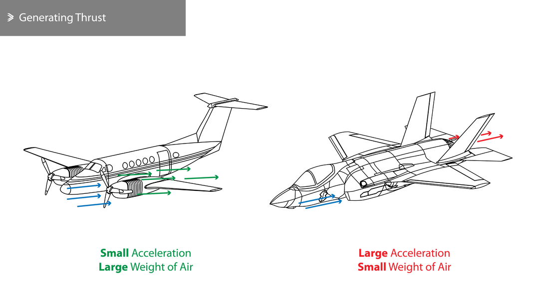
A turbojet works on the same principle as a piston engine driving a propeller. Both propel an aircraft by pushing a large mass of air backwards. The main difference is that a turbojet produces a large acceleration using a relatively small mass of air whereas the combination of the propeller and a piston engine produces a relatively small acceleration to a larger mass of air.
Propelling an aircraft using a jet of air constitutes an application of Newton's 3rd law of motion which explains that for every force applied to a body there is an equal and opposite reaction. In this case, the body is the mass of air which is forced to accelerate through the propulsion system. As a result, this acceleration (change in kinetic energy) requires some energy input from the engine to the air and the resulting jet produces an equal and opposite force on the engine towards the desired direction of motion.
Given that all aircraft are powered by accelerating air in the opposite direction, it quickly becomes evident that jet propulsion is applicable to all aircraft and spacecraft regardless of the engine type. However, they can be broadly categorised into those producing internal acceleration (turbofan, turbojet, etc) and those producing external acceleration (turboprop, etc). It is common to exclude turboprops when referring to jet engines, as jet propulsion is inherently an internal acceleration phenomenon based on the acceleration of an air mass and not simply an increase of its pressure.
Given that all aircraft are powered by accelerating air in the opposite direction, it quickly becomes evident that jet propulsion is applicable to all aircraft and spacecraft regardless of the engine type. However, they can be broadly categorised into those producing internal acceleration (turbofan, turbojet, etc) and those producing external acceleration (turboprop, etc). It is common to exclude turboprops when referring to jet engines, as jet propulsion is inherently an internal acceleration phenomenon based on the acceleration of an air mass and not simply an increase of its pressure.
1.4 Producing Thrust
The jet engine receives a known quantity of air per unit of time at a given speed. As the air travels through the engine, fuel is injected, it combusts and the release of energy increases the speed of exhaust gases which return to the atmosphere. Given that:
\(V_0\) is the intake air speed
\(M_a\) is the mass of intake air per unit of time
\(M_F\) is the mass of fuel injected per unit of time
\(V_j\) is the exhaust air speed
We can define:
\(M_a \cdot V_0\) as the momentum of intake air
\((M_a+M_F) \cdot V_j\) as the momentum of exhaust air and
\((M_a+M_F) \cdot V_j-M_a \cdot V_0\) as the change of momentum
However, we know that change of momentum per unit of time is equal to the force that caused it in the first place, so that:
\(F=(M_a+M_F) \cdot V_j-M_a \cdot V_0\)
Remember that Newton's second law of motion states that a body's rate of change in momentum is equal to the net force acting on it. In this example, it means that the force shall be equal to the thrust produced:
\(T=F\)
As will be discussed further, the mass of fuel injected is significantly lower than the mass of air, so the equation can be reduced with no significant error to:
\(T=M_a \cdot V_j-M_a \cdot V_0\) or \(T=M_a \cdot (V_j-V_0)\)
From this, it becomes obvious that the thrust generated is proportional to the mass of air going into the engine and the change of speed achieved between intake and exhaust. This is, of course, a simplified relationship and we will later discuss how pressure difference of the exhaust gases also contributes to the thrust being produced.
1.5 Jet Engine Types
Jet engines and propulsion systems in general can be categorised into six categories that vary in complexity and achievable thrust ratings. We are only including a quick overview of each one of them to enable you to understand the key differences and what some of the main advantages and disadvantages are.
Ramjet
The ramjet is the simplest form of jet engine that doesn't include any rotating parts. It is effectively a tube with a diverging intake and diverging-converging or simply converging exhaust. When a ramjet is externally moved at a sufficient speed, air is sucked, reducing in speed and increasing in pressure in the diverging intake. The total energy is then increased following the injection and combustion of fuel. The exhaust gases produced are accelerated through the nozzle and are released in the atmosphere.
Despite being simple to manufacture and assemble, the ramjet requires an initial acceleration via external means and is therefore not used to power aircraft. It is commonly used to power missiles or other remotely-controlled devices that are launched from aircraft already in flight. Lorin's engine shown in chapter 1.2 is effectively the simplest form of a ramjet.
Even though pure ramjets are not frequently encountered nowadays, some are equipped with a variable intake that allows them to operate more efficiently over a wider range (<Mach 3 and >Mach 5).
Even though pure ramjets are not frequently encountered nowadays, some are equipped with a variable intake that allows them to operate more efficiently over a wider range (<Mach 3 and >Mach 5).
Pulsejet
As the name suggests, pulsejets operate by combusting fuel in pulses. It can be run statically and it can be manufactured with few or no moving parts. Its structure is largely similar to that of a ramjet but is often more robust due to the higher operating pressures. The intake duct is often equipped with a series of spring-loaded valves.
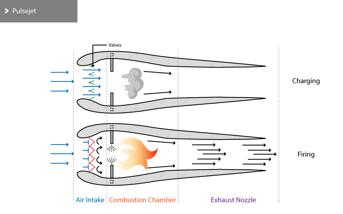
When the pressure inside the engine is equal to the atmospheric, the valves are open allowing air to enter and be combusted. The release of the combustion products causes the rise of the pressure inside the chamber which forces the valves shut and allows the exhaust gases to leave from the back of the engine. The pressure subsequently drops allowing the valves to open again and the cycle repeats.
Pulsejets were used on German 'flying bombs' during World War II, but it is generally unsuitable for aircraft due to its low efficiency and some manufacturing and operational issues. Engines based on the pulsejet design have been manufactured for use on helicopters.
Pulsejets were used on German 'flying bombs' during World War II, but it is generally unsuitable for aircraft due to its low efficiency and some manufacturing and operational issues. Engines based on the pulsejet design have been manufactured for use on helicopters.
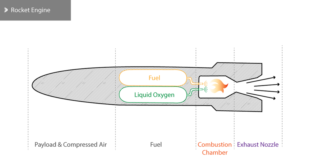
Rocket Engine
Even though rocket engines share the same jet propulsion principles, they differ from all other types in the sense that they don't use atmospheric air for their operation. Rocket engines store the required oxygen and fuel inside their shell, mixing them to specific proportions and combusting them to generate thrust. Rocket engines most commonly provide propulsion to exit the atmosphere and even in such cases their operation is usually short. Small rocket engines have been used to provide additional thrust during take-off of aircraft in extreme or dangerous circumstances.
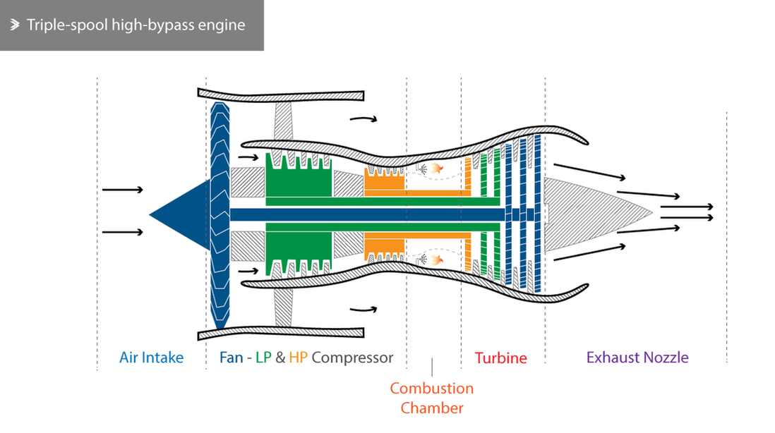
Gas Turbine (Turbofans & Turbojets)
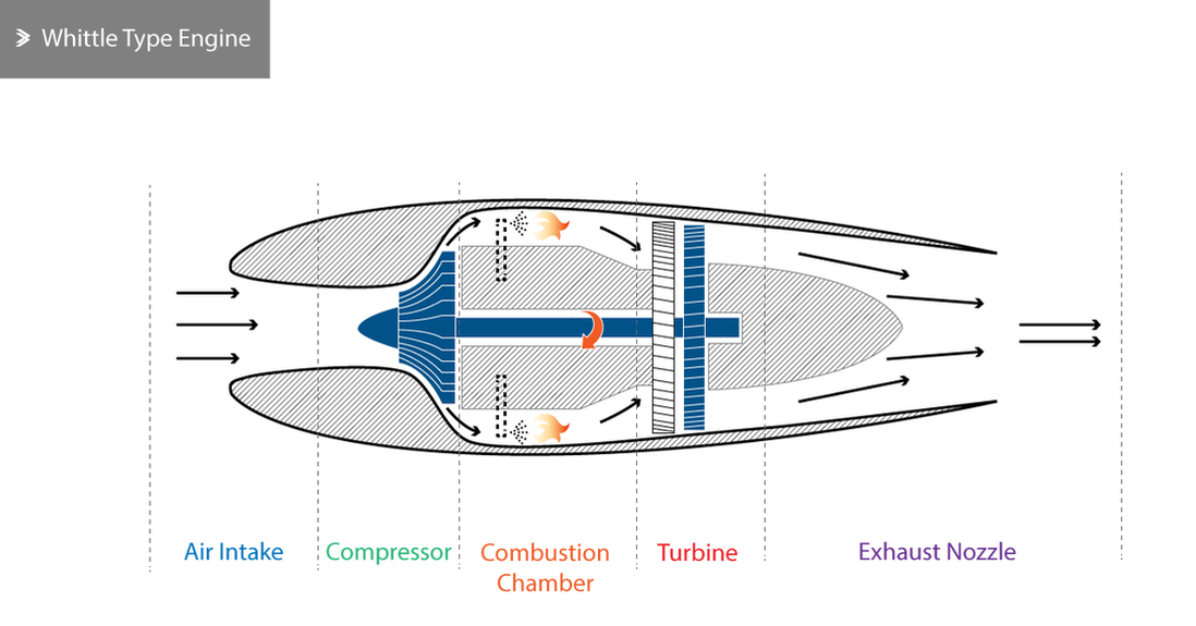
Many of the drawbacks associated with rocket engines and ramjets are addressed by the gas turbine engine. The introduction of a compressor allows for thrust to be generated from static or low-speed conditions and leads to air being accelerated to 1,400mph by the time it leaves the combustion chamber. However, another key difference is that part of the energy is absorbed by a turbine, which in turn drives the compressor.
In principle, the gas turbine engine is simple; the only moving parts are the compressor and the turbine with one or more combustion chambers located in-between. Nevertheless, the gas turbine had to overcome multiple aerodynamic and thermodynamic issues associated with the very high operating temperatures of the combustion chambers and the turbine, the variable amounts of air going through and the design of the turbine itself.
In principle, the gas turbine engine is simple; the only moving parts are the compressor and the turbine with one or more combustion chambers located in-between. Nevertheless, the gas turbine had to overcome multiple aerodynamic and thermodynamic issues associated with the very high operating temperatures of the combustion chambers and the turbine, the variable amounts of air going through and the design of the turbine itself.
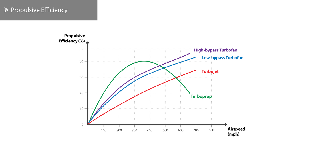
It is worth noting that for speeds under 450mph, the simple gas turbine has inferior efficiency when compared to a piston-driven propeller engine if we assume that the propulsive efficiency is directly related to the airspeed. Gas turbine engines can be broadly categorised based on the following features:
Based on how the energy is utilised
Based on the flow path
Based on the number of shafts between the compressor and the turbine
All referring to coaxial shafts that help improve the efficiency by allowing different sections of the compressor/turbine to rotate at different speeds.
Based on how the energy is utilised
- Turbojets/Turbofans - using the energy from combustion to create a propulsive jet
- Turboprops - using all or most of this energy to rotate a propeller
Based on the flow path
- Single/plain flow (i.e. Turbojets) - where all sucked air goes through the same state changes by the time it reached the exhaust
- Double flow (i.e. Turbofans) - where part of the flow is only slightly compressed initially and then joins the core flow at the exhaust.
Based on the number of shafts between the compressor and the turbine
- Single-spool
- Double-spool
- Triple-spool
All referring to coaxial shafts that help improve the efficiency by allowing different sections of the compressor/turbine to rotate at different speeds.
Turbo/ramjet & Turbo-rocket Engines
Turbo-ramjets combine the turbojet for cruise speeds typically less than Mach 3 and the ramjet for speeds that can be as high as 5 times the speed of sound (Mach 5). The turbo/ramjet achieves such performance at high speeds by shutting down and bypassing the core of the turbojet when a speed of Mach 3 or above is reached to guide all the flow to the afterburner which acts as a combustion chamber.
The turbo-rocket is similar to the turbo-ram with the exception that it also requires a liquid oxygen supply. A fuel-rich mixture with oxygen is combusted to power the turbine and then combusted again in the afterburner. Turbo-rockets are lighter and more compact than turbo-ram jets and are suitable for very high altitude, high-speed travel or space launches as they can provide continuous and high thrust for relatively short periods of time. One of the key drawbacks is the high thrust specific fuel consumption (TSFC).
The turbo-rocket is similar to the turbo-ram with the exception that it also requires a liquid oxygen supply. A fuel-rich mixture with oxygen is combusted to power the turbine and then combusted again in the afterburner. Turbo-rockets are lighter and more compact than turbo-ram jets and are suitable for very high altitude, high-speed travel or space launches as they can provide continuous and high thrust for relatively short periods of time. One of the key drawbacks is the high thrust specific fuel consumption (TSFC).
1.6 Jet Engine Design
The design of a new engine and the planning required for mass manufacturing are both tasks involving considerable amounts of time. Taking into account the manufacturing and testing of the prototype engines all the way to the delivery of the first engine to enter service, programmes often span over a decade or more. Nowadays, most engines excluding research and concept engines, are based on the previous designs of each manufacturer which can shorten the design time and reduce the development cost significantly. When multiple engines share the same basic design but differ in features and performance characteristics, they are referred to as a family of engines.
Designing a jet engine requires solutions to many engineering challenges around aerodynamics, thermodynamics, electronics and reliability which are almost always interdependent. Examining the effect of different flow conditions is often a key task, whilst the extremely high temperatures pose challenges in terms of the materials being used and the cooling systems. Strength, fatigue and reliability are all mutually vital given that parts of the engine are exposed to repeated and prolonged aerodynamic, centrifugal & thermal loading whilst the danger of corrosion and erosion should also be taken into account.
Once a prototype engine is assembled, it goes through rigorous ground testing, which often highlights performance or design issues in certain conditions. During the certification process, a vast range of parameters are tested and validated, including:
and many more. If successful, the engine is mounted on an aircraft for test flights which check the performance of the engine combined with avionic controls. Finally, the engine is mounted on the aircraft that it was designed for and once certified, it is ready to enter the market.
Designing a jet engine requires solutions to many engineering challenges around aerodynamics, thermodynamics, electronics and reliability which are almost always interdependent. Examining the effect of different flow conditions is often a key task, whilst the extremely high temperatures pose challenges in terms of the materials being used and the cooling systems. Strength, fatigue and reliability are all mutually vital given that parts of the engine are exposed to repeated and prolonged aerodynamic, centrifugal & thermal loading whilst the danger of corrosion and erosion should also be taken into account.
Once a prototype engine is assembled, it goes through rigorous ground testing, which often highlights performance or design issues in certain conditions. During the certification process, a vast range of parameters are tested and validated, including:
- Establishing normal and excess operating conditions
- Checking protective mechanisms against variations in fuel temperature, pressure and contamination
- Inclination and gyroscopic load effects
- Starting, acceleration and endurance tests
- Low-temperature starting tests and operation in ice-forming conditions
- Ingestion of rain and hail
- Bird strike and injection
- Compressor and turbine engine failure tests
and many more. If successful, the engine is mounted on an aircraft for test flights which check the performance of the engine combined with avionic controls. Finally, the engine is mounted on the aircraft that it was designed for and once certified, it is ready to enter the market.
1.7 Materials
Several materials and pioneering manufacturing technologies have been introduced to cover the needs of modern jet engines. Material selection is driven by the need for parts to be light or at least have a very good strength to weight ratio, to be creep resistant at high temperatures, as well as resist corrosion and erosion. Nickel- and chromium-rich stainless steels were historically good candidates for use in jet engines, but the introduction of superior titanium alloys and superalloys, including nickel or cobalt alloys, since the 60s has raised the bar of what is achievable in terms of operating pressures and temperatures.
Nowadays, carbon-fibre can be found in critical components such as the fan offering the same or superior performance for reduced weight. In all cases, the evolution of the manufacturing processes in tandem with the introduction of new materials was crucial in enabling certain materials to be used and certain parts to perform the way they are able to. The introduction of tiny cooling channels in turbine blades or of a semi-hollow internal section in fan blades are examples of such advances. Most recently, metal Additive Manufacturing (AM) has been introduced in jet engine manufacturing lines, adding some design freedom or producing lighter parts faster and often from materials which are difficult to manufacture by traditional means. So far, AM is being used for a small number of non-critical parts including the fuel nozzles of the GE LEAP engines. The use of AM for the nozzles allowed a single part to replace what was previously a 20-part assembly, yielding an overall weight saving of 25%.
Nowadays, carbon-fibre can be found in critical components such as the fan offering the same or superior performance for reduced weight. In all cases, the evolution of the manufacturing processes in tandem with the introduction of new materials was crucial in enabling certain materials to be used and certain parts to perform the way they are able to. The introduction of tiny cooling channels in turbine blades or of a semi-hollow internal section in fan blades are examples of such advances. Most recently, metal Additive Manufacturing (AM) has been introduced in jet engine manufacturing lines, adding some design freedom or producing lighter parts faster and often from materials which are difficult to manufacture by traditional means. So far, AM is being used for a small number of non-critical parts including the fuel nozzles of the GE LEAP engines. The use of AM for the nozzles allowed a single part to replace what was previously a 20-part assembly, yielding an overall weight saving of 25%.
Back to Aeolus directory |
Next up: 2. Working Cycle |

|