
Back to Aeolus directory
2. Working Cycle
2.1 Ideal Working Cycle
2.2 Ideal Efficiency
2.3 Ideal Work
2.4 Increasing Work
2.5 Real Working Cycle
2.6 Real Efficiency
2.7 Real Operation
2.1 Ideal Working Cycle
The working cycle of a jet engine is largely similar to that of a piston engine, with the main difference being that combustion in the piston engine takes place at constant volume, whilst combustion in a jet engine takes place under constant pressure. In the piston engine, intake, compression, combustion, expansion and discharge take place sequentially as the piston is involved in all stages. In a jet engine (excluding pulsejets), all these phases take place simultaneously and continuously across a number of different components.
Ideal jet engines operation is described by the Brayton cycle and can be broken down in the following thermodynamic processes:
[1 - 2] Adiabatic compression
[2 - 3] Isobaric combustion
[3 - 4] Adiabatic expansion
[4 - 1] Isobaric heat rejection
To enable these state changes to happen, the jet engine must be equipped with an intake, compressor, combustion chamber, turbine and exhaust nozzle. Isobaric refers to a process that is carried out at constant pressure, whereas adiabatic refers to a process during which no heat transfer occurs between the system and the environment.
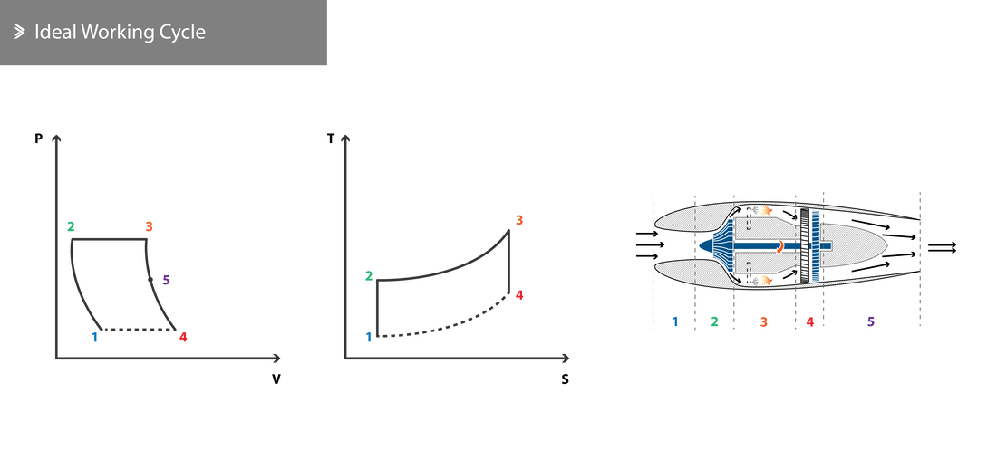
Air enters the engine through the intake as the compressor sucks it in and using its optimised geometry, arrangement and rotational speed compresses it [1-2].
The compressed air enters the combustion chamber where fuel is sprayed and the mixture is combusted. Ideally, the combustion process is isobaric [2-3].
The exhaust gases enter the turbine and exert forces on the rotors, causing them to rotate. The rotation of the turbine subsequently rotates the compressor through the common axis/axes between spools. This way, part of the energy is harvested and used to power the compressor [3-5].
The final discharge takes place through the exhaust nozzle where the pressure and temperature fall, but velocity increases as it exits the engines [5-4]. Once the exhaust gases leave the engine, the remainder of the heat rejection process takes place in the atmosphere, noted by the dashed lines.
In order to achieve the states of the Brayton cycle outlined, the following requirements must be met:
Of course, it is impossible to fully satisfy all three requirements and we will, in fact, establish that the real working cycle differs in many aspects. To be able to quantify those differences, we will use the Temperature-Entropy (T-S) diagram shown above from which we can derive the following relationships using basic thermodynamics:
The compressed air enters the combustion chamber where fuel is sprayed and the mixture is combusted. Ideally, the combustion process is isobaric [2-3].
The exhaust gases enter the turbine and exert forces on the rotors, causing them to rotate. The rotation of the turbine subsequently rotates the compressor through the common axis/axes between spools. This way, part of the energy is harvested and used to power the compressor [3-5].
The final discharge takes place through the exhaust nozzle where the pressure and temperature fall, but velocity increases as it exits the engines [5-4]. Once the exhaust gases leave the engine, the remainder of the heat rejection process takes place in the atmosphere, noted by the dashed lines.
In order to achieve the states of the Brayton cycle outlined, the following requirements must be met:
- The compressor, turbine and the respective casing must be manufactured in such a way that allows for adiabatic compression and expansion (i.e. perfectly insulated so that no heat transfer taking place)
- Combustion must be carried out under constant pressure conditions
- Ideal gas law must be valid in the entire temperature range
Of course, it is impossible to fully satisfy all three requirements and we will, in fact, establish that the real working cycle differs in many aspects. To be able to quantify those differences, we will use the Temperature-Entropy (T-S) diagram shown above from which we can derive the following relationships using basic thermodynamics:
Adiabatic Compression
\[\dfrac{T_2}{T_1}=\left(\dfrac{P_2}{P_1}\right)^\dfrac{\gamma-1}{\gamma}\]
where \(\gamma\) is:
\[\gamma=\frac{C_P}{C_V}\]
and \(C_P\) is defined as the specific heat constant for constant pressure (i.e. the amount of heat required to raise the temperature of a 1 kg mass by one degree Celsius at constant pressure) and \(C_V\) is the specific heat constant for constant volume.
The work is then:
\[W_{12}=C_V\cdot (T_2-T_1)\]
Isobaric Combustion
\[P_2=P_3\]
And the heat generated is:
\[Q=C_P\cdot (T_3-T_2)\]
Adiabatic Expansion
\[\dfrac{T_3}{T_4}=\left(\dfrac{P_3}{P_4}\right)^\dfrac{\gamma-1}{\gamma}\]
And the work is:
\[W_{34}=C_V\cdot (T_3-T_4)\]
2.2 Ideal Efficiency
The ideal efficiency can be defined as:
\[\eta=\dfrac{W_{out}}{Q_{in}}=\dfrac{W_{34}-W_{12}}{Q_{23}}\]
And taking \(P_1=P_4\) into account, this can be rearranged to:
\[\eta=1-\dfrac{T_1}{T_2}=1-\dfrac{T_4}{T_3}=1-\dfrac{1}{R^{(\gamma-1)/\gamma}}\]
where \(R\) represents the compression ratio \(R=\dfrac{P_2}{P_1}\)
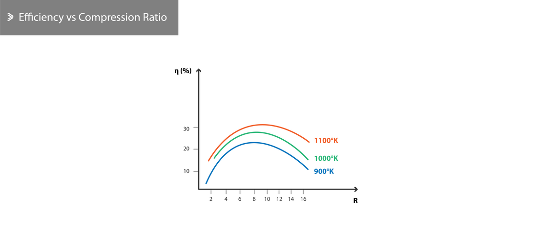
This relationship suggests that the efficiency depends on the compression ratio alone and not the combustion temperature, which is of course not the case in real engines.
\[\eta=\dfrac{W_{out}}{Q_{in}}=\dfrac{W_{34}-W_{12}}{Q_{23}}\]
And taking \(P_1=P_4\) into account, this can be rearranged to:
\[\eta=1-\dfrac{T_1}{T_2}=1-\dfrac{T_4}{T_3}=1-\dfrac{1}{R^{(\gamma-1)/\gamma}}\]
where \(R\) represents the compression ratio \(R=\dfrac{P_2}{P_1}\)
This relationship suggests that the efficiency depends on the compression ratio alone and not the combustion temperature, which is of course not the case in real engines.
2.3 Ideal Work
Therefore, we can define the useful work to be:
\[W=C_V(T_3-T_4)-C_V(T_2-T_1) \Leftrightarrow \]
\[C_V\times T_1 \bigg[ \dfrac{T_3}{T_1}\left(1-\dfrac{T_4}{T_3}\right)-\left(\dfrac{T_2}{T_1}-1 \right) \bigg] \Leftrightarrow \]
\[C_V\times T_1 \bigg[ \dfrac{T_3}{T_1}\left(1-\dfrac{T_4}{T_3}\right)-\left(\dfrac{T_3}{T_4}-1 \right) \bigg] \Leftrightarrow \]
\[C_V\times T_1 \bigg[ \dfrac{T_3}{T_1}\left(1-\dfrac{1}{R^{(\gamma-1)/\gamma}}\right)-\left(R^{(\gamma-1)/\gamma}-1 \right) \bigg] \]
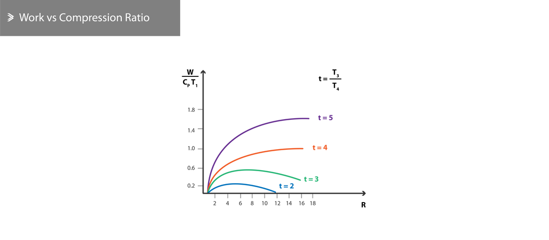
Which shows that the useful work is a function of the combustion temperature \(T_3\) and the compression ratio \(R\). Therefore, the following can be concluded theoretically:
\[W=C_V(T_3-T_4)-C_V(T_2-T_1) \Leftrightarrow \]
\[C_V\times T_1 \bigg[ \dfrac{T_3}{T_1}\left(1-\dfrac{T_4}{T_3}\right)-\left(\dfrac{T_2}{T_1}-1 \right) \bigg] \Leftrightarrow \]
\[C_V\times T_1 \bigg[ \dfrac{T_3}{T_1}\left(1-\dfrac{T_4}{T_3}\right)-\left(\dfrac{T_3}{T_4}-1 \right) \bigg] \Leftrightarrow \]
\[C_V\times T_1 \bigg[ \dfrac{T_3}{T_1}\left(1-\dfrac{1}{R^{(\gamma-1)/\gamma}}\right)-\left(R^{(\gamma-1)/\gamma}-1 \right) \bigg] \]
Which shows that the useful work is a function of the combustion temperature \(T_3\) and the compression ratio \(R\). Therefore, the following can be concluded theoretically:
- The useful work is maximised when \(T_2=T_4\)
- For a given \(R\), the work increases as \(T_3\) increases
- For a given \(T_3\), the work has an optimum \(R\) value- further increasing it will result in a decrease in the useful work.
2.4 Increasing Work
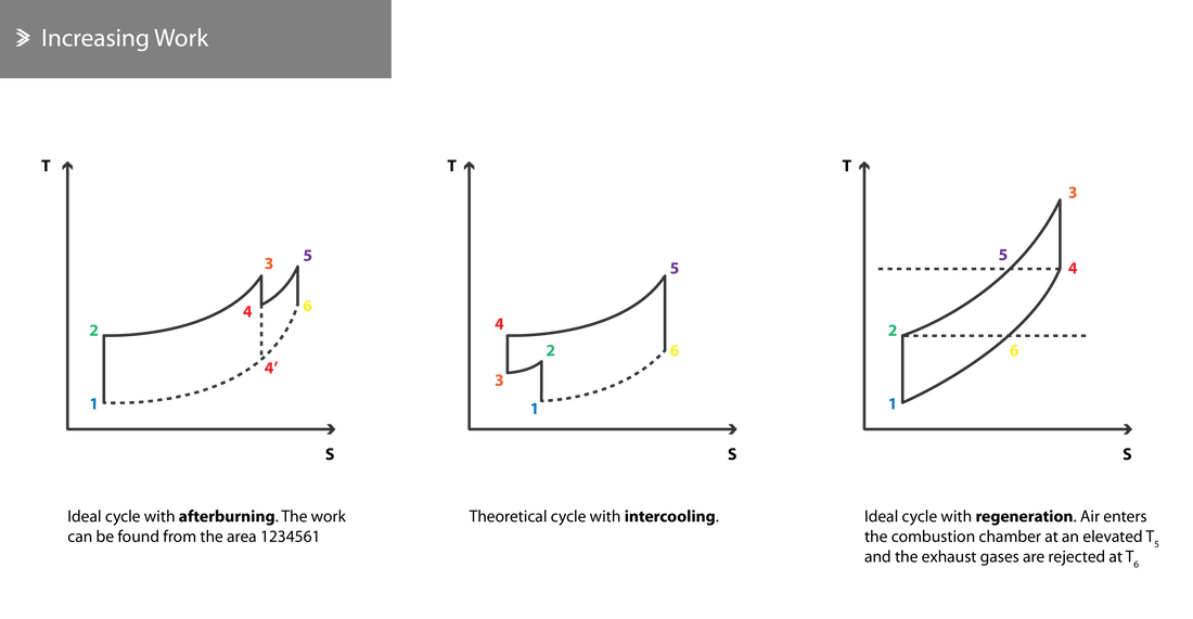
The work can be calculated by the area of the working cycle diagram between points (1-2-3-4-1). Line 1-4 corresponds to atmospheric pressure and 2-3 corresponds to the max compression pressure achievable by the respective engine.
Taking these into account, we can establish the following two constraints; point 1 is fixed as it corresponds to the atmospheric conditions and point 3 is also fixed as it depends on the max achievable pressure and the max temperature that the used materials can safely withstand. Subsequently, optimising the cycle lies upon shifting points 2 and 4. There are three main options to achieve that:
Taking these into account, we can establish the following two constraints; point 1 is fixed as it corresponds to the atmospheric conditions and point 3 is also fixed as it depends on the max achievable pressure and the max temperature that the used materials can safely withstand. Subsequently, optimising the cycle lies upon shifting points 2 and 4. There are three main options to achieve that:
- Using an afterburner or reheating
- Using an intercooler
- Using regeneration to further increase the air temperature before it enters the combustion chamber
Afterburning
In an afterburner, additional fuel is injected in the exhaust gas mixture after leaving the turbine. The combustion of this mixture contributes towards the increase of the exhaust gas velocity. The oxygen required for this secondary combustion primarily comes from previously unburned, bleed air that was used to cool parts of the engine and at that point re-enters the core flow.
Theoretically, the work produced is maximised when:
\[\dfrac{T_3}{T_1}=\sqrt{\dfrac{T_2}{T_1}}\]
However, the combustion efficiency in the afterburner is relatively low, which results in the overall efficiency being lower than that of the simple working cycle. The performance gains can be significant though and the use of an afterburner can increase the static thrust by up to 70%.
Intercooling
During intercooling, the compression process is split into two sections and the compressed air is cooled in-between these sections. Cooling the air takes the temperature down to its original state before it is compressed again. Cooling the air can be realised by introducing a heat exchanger or by spraying alcohol which absorbs heat as it evaporates.
Theoretically, the work produced can be found through the 1-2-3-4-5-6 area in the schematic below and is maximised when:
\[\sqrt{\dfrac{T_2}{T_1}}=\dfrac{T_4}{T_3}\]
Intercoolers such as the ones described above are not found in aircraft engines due to the additional weight and complexity counteracting some of the work output gains, hence making it more suitable for static engines. However, the principle finds application in concept engines such as the SABRE engine and involved supercooling the intake air before it enters the compressor.
Regeneration
In regeneration setups, some of the energy of the hot exhaust gases is used to raise the temperature of the compressed air before it enters the combustion chamber. For a start, this is possible to do due to the fact that \(T_4\) is greater than \(T_2\).
Using regeneration, the efficiency of the working cycle increases as:
\[\eta=\dfrac{C_P(T_3-T_4) - C_P(T_2-T_1)}{C_P(T_3-T_5)}\]
which can be simplified to:
\[\eta=1-\dfrac{T_2}{T_3}\]
This shows that the efficiency change depends both on the compression temperature and the combustion temperature. The work produced remains theoretically the same as the efficiency increases when regeneration is used. In reality, the work slightly drops due to the energy losses involved in heating the compressed air.
2.5 Real Working Cycle
In reality, it is impossible to satisfy all the requirements of an ideal working cycle. These can be summarised to be:
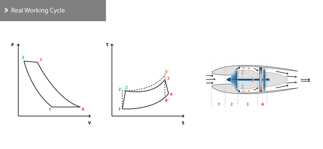
Primarily due to the reasons above, the real working cycle is distinctly different from the ideal case. We will now look at the various sources of energy losses and the efficiencies that define them.
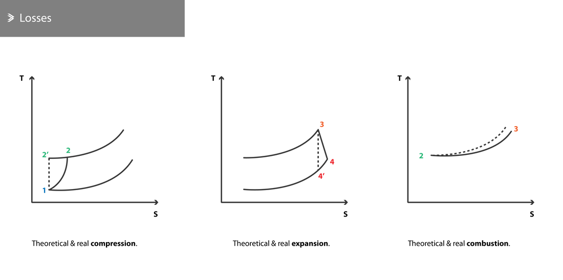
- The compression of the air in the compressor and its expansion in the turbine cannot take place adiabatically, due to friction and heat losses.
- During combustion, pressure drops due to the resistance to the flow.
- The compressor requires more energy than the theoretically calculated requirement to rotate at a given speed.
- Other systems, including generators, pumps, auxiliary systems, etc also require some energy which needs to be extracted from the turbine.
- The specific heat \(C_P\) of air is different than that of the exhaust gases and varies with temperature along the engine. Furthermore, \(\gamma\) does not remain constant and varies with the temperature changes.
Primarily due to the reasons above, the real working cycle is distinctly different from the ideal case. We will now look at the various sources of energy losses and the efficiencies that define them.
Compressor Losses
A large proportion of the energy which the compressor receives from the fan does not contribute towards the compression of the air and is converted to heat due to friction. As a result, the temperature of the air exiting the compressor is higher than calculated theoretically.
In order to estimate the energy loss in this case, the compressor efficiency is introduced which is equal to the fraction of the ideal compressor work over the real compressor work.
For reference, this is found to be ~0.80 for jet engines with centrifugal compressors and ~0.85 for axial compressors.
Turbine Losses
For the same reasons described above, the work extracted from the exhaust gases during their expansion in the turbine and exhaust nozzle is less than the ideal. Further to that, the exhaust temperature is also higher in reality.
In order to estimate the energy loss in this case, the turbine efficiency is introduced which is equal to the fraction of the real turbine work over the ideal turbine work.
In order to estimate the energy loss in this case, the turbine efficiency is introduced which is equal to the fraction of the real turbine work over the ideal turbine work.
Combustion Losses
Various layouts exist for the combustion chamber aiming to improve the mixing of the fuel with the compressed air and optimise the combustion process, but all exert some resistance to the flow. As a result, a slight drop in pressure along the length of the chamber is observed, which can be as high as 8%.
Mechanical Losses
As power is transmitted from the turbine to the compressor through one or more shafts, mechanical losses due to friction come into play. Bearings and gears, where applicable, can have a significant influence on this. These losses do not typically exceed 1% of the power generated, yielding an efficiency of 0.99.
Specific Heat Changes
The value of \(C_P\) increases as the temperature increases. For reference, it can vary from 1.00 kJ/kg °C (0.24 BTU/lb °F) for air at atmospheric conditions to 1.23 kJ/kg °C (0.30 BTU/lb °F) for air at 1500 degrees Celsius. Further to that, it is worth noting that the specific heat capacity is also affected by the fuel-to-air ratio of the combustion mixture.
However, as the temperature increases, the value of \(\gamma\) decreases. In many calculations, it is acceptable to use a value of \(\gamma=1.40\) for compression and \(\gamma=1.33\) for combustion and expansion.
For this and all other reasons presented above, we need to produce a new cycle diagram. Even though a representative one is shown below, it can vary noticeably as the efficiencies vary across different components in different engines.
2.6 Real Efficiency
Calculating the efficiency of a real engine is a complex task due to the number of inefficiencies involved and the difficulty in accurately estimating some of these. However, the following key points can be highlighted:
- The real efficiency increases as the compression ratio increases
- The efficiency of the compressor and the turbine are crucial in increasing the overall real efficiency
- The overall efficiency increases as the \(\frac{T_3}{T_1}\) ratio increases (either as \(T_3\) decreases, as \(T_1\) increases or a combination of both with the latter being dependent on the weather and altitude)
- For a given combustion temperature \(T_3\), the efficiency reaches its maximum at a specific compression ratio. Increasing this ratio further leads to a drop in efficiency, which is also discussed below.
The useful work is the difference between the total energy in the engine minus the energy used up in the turbine to drive the compressor. As the compression ratio increases so does the compressor efficiency, whilst resulting in a slight reduction in fuel requirement as the temperature \(T_2\) at the exit of the compressor increases. For a given \(T_3\), increasing the compression past a certain point, increases the compression work which is relatively larger than the benefit induced from the increase of \(T_2\) alone. As a result, the overall efficiency drops.
2.7 Real Operation
In order to start up an engine, it is necessary to use some kind of external power to cause an initial rotation and subsequently flow through the engine. The Auxiliary Power Unit (APU) is a small jet engine commonly found in the tail of civil aircraft that can be started electrically and is then able to start up the main engines mechanically.
The air is compressed to a set pressure and then guided to the combustion chambers. In reality, the air going through each combustion chamber is significantly more than the amount of air required for combustion. In earlier, simpler jet engines, the ratio of air-to-fuel by weight was 60:1, whilst the required amount is approximately 14:1. In high bypass engines, the amount of air sucked is, of course, higher but not all the air is compressed and burned.
In the combustion chambers, the fuel is injected under high pressure and the mixture ignites due to the high temperatures. Spark plugs are used during startup only to initiate combustion. The actual combustion temperature can be as high as 1800°C, but the mixing with bleed/cooling air brings this down to around 1000°C.
The exhaust gases enter the turbine, which absorbs part of their energy in order to drive the compressor and/or fan, if applicable.
The second part of the expansion takes place in the exhaust nozzle, which accelerates the flow to speeds up to 1400 mph.
For an average jet engine, it is necessary to suck around 0.5 kg (1.1 lbs) of air per second to produce around 200 N (45 lbf). Conversely, around 75 kW (100hp) of power is required to compress 0.5 kg of air. This means that a 5000 lbf (22.2 kN) engine requires around 45 kg of air per second while the compressor requires around 7.5 MW (10100 hp).
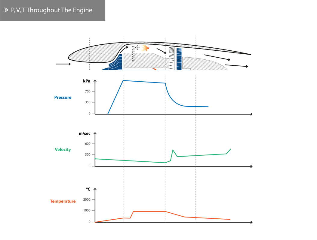
Finally, the graph below shows the changes in pressure, velocity and temperature across an engine with no bypass.
The air is compressed to a set pressure and then guided to the combustion chambers. In reality, the air going through each combustion chamber is significantly more than the amount of air required for combustion. In earlier, simpler jet engines, the ratio of air-to-fuel by weight was 60:1, whilst the required amount is approximately 14:1. In high bypass engines, the amount of air sucked is, of course, higher but not all the air is compressed and burned.
In the combustion chambers, the fuel is injected under high pressure and the mixture ignites due to the high temperatures. Spark plugs are used during startup only to initiate combustion. The actual combustion temperature can be as high as 1800°C, but the mixing with bleed/cooling air brings this down to around 1000°C.
The exhaust gases enter the turbine, which absorbs part of their energy in order to drive the compressor and/or fan, if applicable.
The second part of the expansion takes place in the exhaust nozzle, which accelerates the flow to speeds up to 1400 mph.
For an average jet engine, it is necessary to suck around 0.5 kg (1.1 lbs) of air per second to produce around 200 N (45 lbf). Conversely, around 75 kW (100hp) of power is required to compress 0.5 kg of air. This means that a 5000 lbf (22.2 kN) engine requires around 45 kg of air per second while the compressor requires around 7.5 MW (10100 hp).
Finally, the graph below shows the changes in pressure, velocity and temperature across an engine with no bypass.

|