Back to Aeolus directory
3. Intake & Compression
3.1 Intake Types
3.2 Compressor Types
3.3 Centrifugal: Principles of Operation
3.4 Centrifugal: Design & Manufacture
3.5 Axial: Principles of Operation
3.6 Axial: Design & Manufacture
3.7 Axial: Operating Conditions
3.8 Axial: Surge
3.9 Axial: Stall
3.10 Axial: Flow Control
The air intake is one of the most important parts of the engine and its significance is even greater for high-speed aircraft. The intake should be designed in such a way that provides minimal disruption to the flow. In addition to that, the flow to the compressor should be as uniform as possible in order to minimise pressure losses and maximise the useful energy. The shape and location of the intake depend on the design of the aircraft as a whole, the number of engines, etc.
3.1 Intake Types
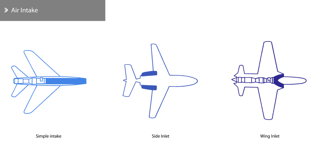
In fighter jets, the engine is usually located within the body of the aircraft, which is shaped around it to create the intake.
In commercial aircraft, the engines are typically mounted underneath the wings or on the side of the fuselage. Therefore, the intake is an integral part of each engine assembly and does not require other changes to the made to the fuselage or wings. Featured in the first commercial airliners in the early 50s, the de Havilland Comet, the engines were integrated within the wings on either side of the fuselage. This is very much a redundant design due to the difficultly in integrating newer (i.e. high bypass engines) with much larger diameters and the added complexity of maintenance and disassembly compared to the current pylon/hardpoint design.
In commercial aircraft, the engines are typically mounted underneath the wings or on the side of the fuselage. Therefore, the intake is an integral part of each engine assembly and does not require other changes to the made to the fuselage or wings. Featured in the first commercial airliners in the early 50s, the de Havilland Comet, the engines were integrated within the wings on either side of the fuselage. This is very much a redundant design due to the difficultly in integrating newer (i.e. high bypass engines) with much larger diameters and the added complexity of maintenance and disassembly compared to the current pylon/hardpoint design.
Generally speaking, the following types of intakes for jet engines can be identified:
- Simple (single) combat jet intake. This is the simplest form of an integrated engine intake in the aircraft body and the most efficient at the same time, being collinear with the central engine axis.
- Double combat jet intake. This consists of two intakes either on the side of the aircraft or at the roots of the wings, as shown above. The intakes meet before the air enters the engine in both cases.
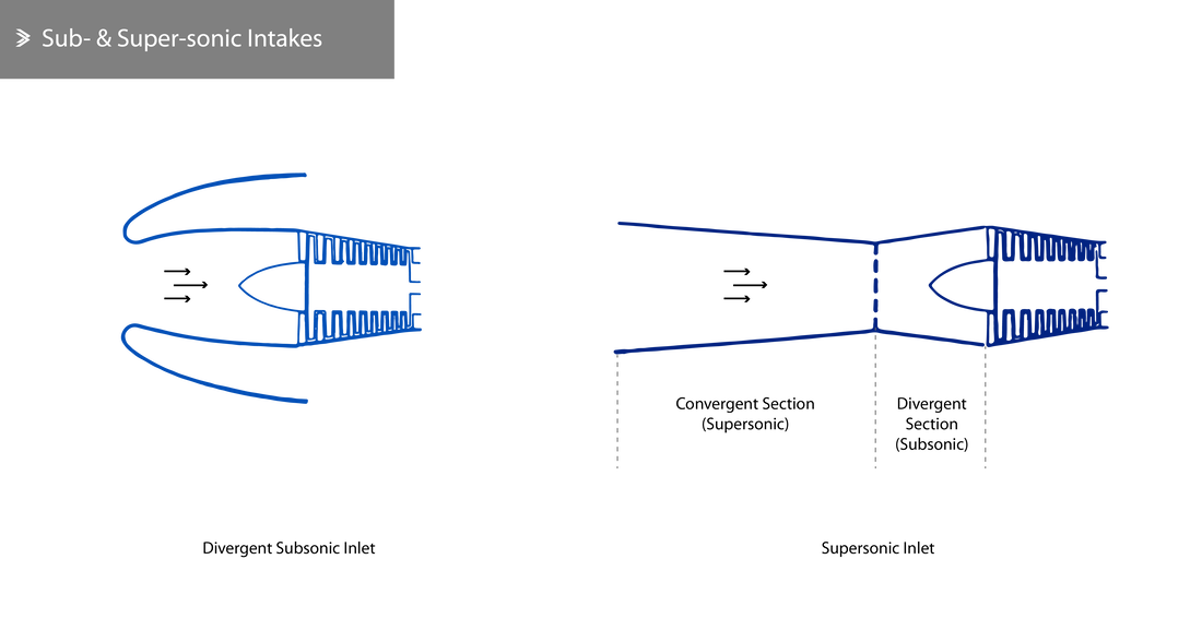
- Subsonic intake. For most commercial applications, the speed of the air before this enters the compressor is typically around Mach 0.5. Due to the fact that most modern aircraft operate at high subsonic speeds, the intake should be diverging slightly.
- Supersonic intake. For the same reason, the intake should initially converge to reduce the speed from supersonic to around Mach 1 and then diverge to further reduce the speed to around Mach 0.5. Inducing shockwaves normal to the intake walls is one of the easiest ways to aerodynamically slow down the flow.
- Variable intakes. These can be implemented either through the use of moving intake surfaces or through the creation of inclined, oblique shockwaves at the intake. Variable intakes are mechanically more complex and heavier that simple supersonic intakes. Both commercial supersonic aircraft to have even been produced, the Concorde and the Tu-144, had variable ramp intakes.
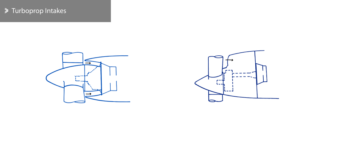
- Turboprop intakes. These are very simple in principle but come in different shapes due to the presence of the propeller. Two common arrangements are shown below.
In certain cases, intake filters may be used to reduce the chance of Foreign Object Damage (FOD). However, it is worth mentioning that the use of filters also introduces pressure losses at the intake and are often very sensitive to ice formation. Excessive wear on a filter and improper maintenance can lead to major compressor damage and their addition, including any control mechanism, add weight which would be difficult to justify in most cases.
For these reasons, the use of filters is limited for combat aircraft, as their intakes are often closer to the ground. Where fitted, the filters are used during taxiing, in certain cases during take-off and during the flight in areas where FOD maybe be likely (i.e. due to flocks of birds etc).
For these reasons, the use of filters is limited for combat aircraft, as their intakes are often closer to the ground. Where fitted, the filters are used during taxiing, in certain cases during take-off and during the flight in areas where FOD maybe be likely (i.e. due to flocks of birds etc).
3.2 Compressor Types
Compressing the air in a jet engine is essentially done only using one of two types of compressors; the centrifugal compressor and the axial compressor.
The centrifugal compressor consists of one or two stages, with each stage using a rotating part (impeller) to accelerate the air and a diffuser to achieve the required temperature increase. The axial compressor consists of multiple stages with alternatives rows of rotating and stationary blades that successively compress the air to the desired pressure.
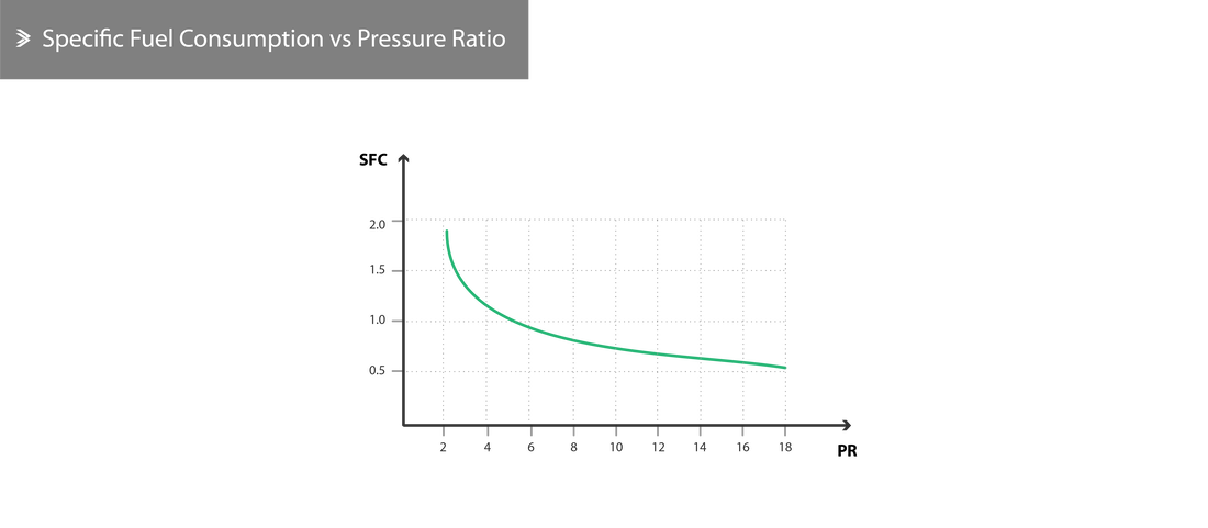
The centrifugal compressor is generally more robust and easier to manufacture. However, axial compressors can suck in a much larger mass of air relative to the intake surface area and can output higher pressure ratios. The increase in airflow capacity through the compressor equals an increase in usable thrust. After all, a higher pressure will boost the engine’s efficiency and lower specific fuel consumption.
3.3 Centrifugal: Principles of Operation
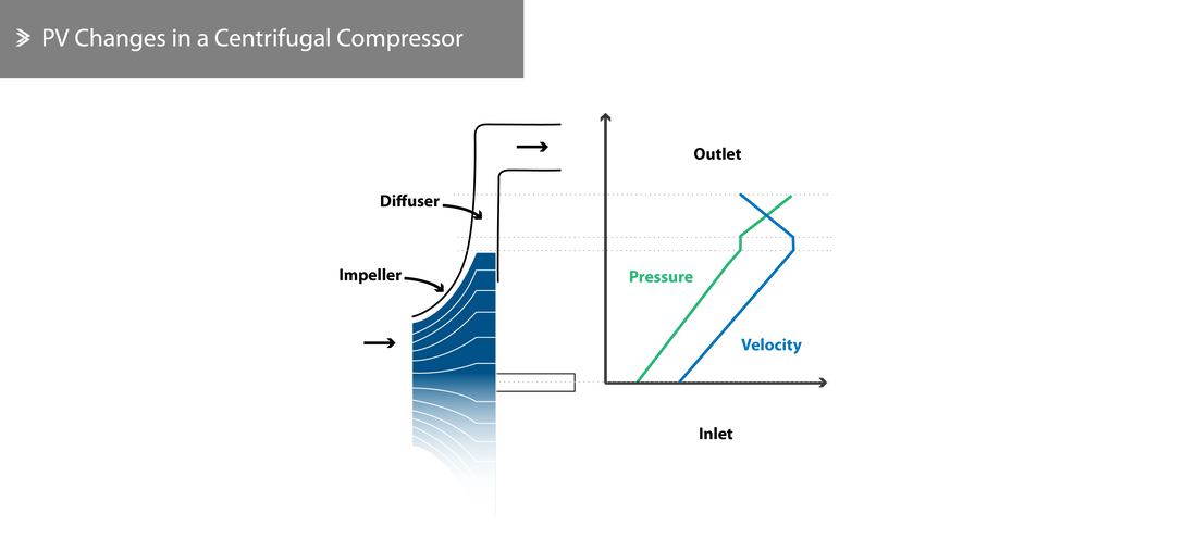
The turbine drives the impeller at high speeds, resulting in a steady suction at its centre. The centrifugal forces that arise push the air outwards, along the paths of the impeller blades, which accelerates the flow, whilst slightly pressurising the air.
As the air leaves the impeller, it goes through diffusers; divergent openings that enable the conversion of the kinetic energy to pressure energy. Centrifugal compressors are often designed so that around half of the pressure increase comes from the impeller and the other half from the diffusers.
As the air leaves the impeller, it goes through diffusers; divergent openings that enable the conversion of the kinetic energy to pressure energy. Centrifugal compressors are often designed so that around half of the pressure increase comes from the impeller and the other half from the diffusers.
The mass of air being compressed and the pressure increase itself depend on the rotational speed of the compressor. For most centrifugal compressors, the blade tip speed may reach 480 m/s (1575 feet/s). The air temperature at the inlet also affect the performance of the compressor; the colder the air the higher the pressure reached for the same given energy input to the compressor.
To maintain high efficiency in the compressor, considerable leakage of air in the space between the impeller and the casing should be avoided by minimising the distance between the two.
To maintain high efficiency in the compressor, considerable leakage of air in the space between the impeller and the casing should be avoided by minimising the distance between the two.
3.4 Centrifugal: Design & Manufacture
The three main elements of a centrifugal compressor are the intake, the impeller and the diffuser vanes. The shaft which connects the impeller to the turbine sits on ball or cylindrical roller bearings and is either manufactured as a single component or assembled from two segments that allow for easier disassembly.
Impeller
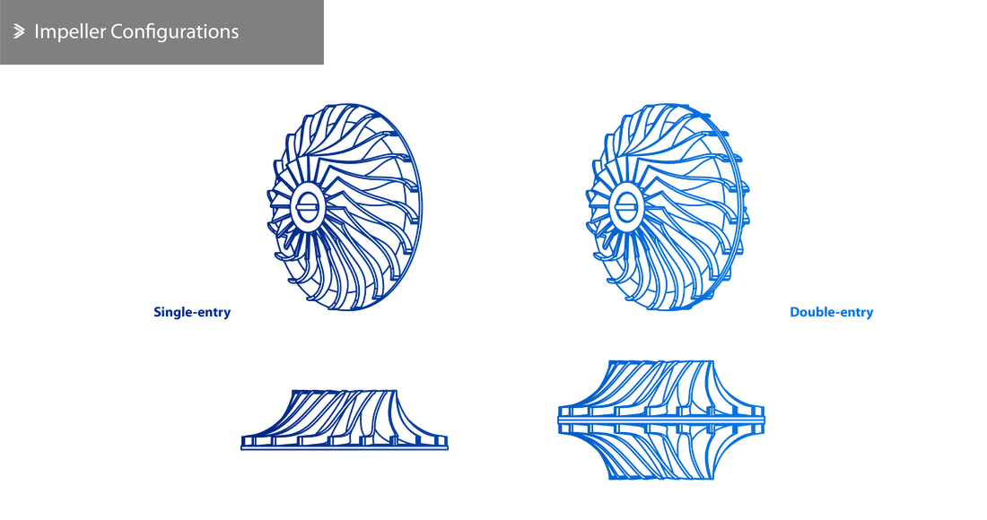
The impeller is often manufactured from a forged disc with radial vanes machined on one or both sides that form divergent channels. The vanes may be curved backwards, even though earlier models featured straight vanes for ease of manufacture. To aid the change in flow from axial (entry) to radial, the vanes at the centre of the impeller are often slightly curved along the direction of the rotation. In some cases, this curvature might not be introduced to the main vanes, but additional ones in-between them.
The choice of impeller is generally driven by the overall design requirements, but the single-entry impeller is considered to offer the optimum suction for the best possible performance in all conditions. This arrangement also harvests the benefits of the ram effect (from the intake velocity) better than the double-entry alternative, thus reducing the danger of stalling at higher altitudes. The use of a double-entry impeller also results in a small temperature increase.
Nonetheless, the diameter of a double-entry impeller required to suck a given mass of air is smaller than that for a single-entry impeller, which subsequently has an effect on the overall engine diameter.
Nonetheless, the diameter of a double-entry impeller required to suck a given mass of air is smaller than that for a single-entry impeller, which subsequently has an effect on the overall engine diameter.
Diffusers
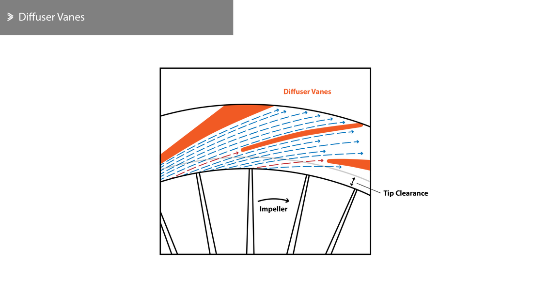
The diffusers may be manufactured as a single component with the impeller casing or in a separate assembly. In both cases, the diffusers consist of a number of vanes positioned tangentially to the impeller perimeter that form divergent cavities to convert the kinetic energy to pressure energy. The inner tip of the vane is tangential to the direction of the flow, as this exits the impeller. The tip clearance is a tightly controlled feature that is crucial for the smooth operation of the engine. A very small clearance can lead to aerodynamic vibrations, which can disturb the flow or cause mechanical vibrations on the impeller.
Losses
As the impeller rotates, the pressure at the front of the vanes is greater than that at the rear. As a result, there is a tendency for some air to travel from the front of the vane to the back through the gap between the impeller and the casing. The escaping air does contribute to some energy losses, which also includes friction losses. Frictional dissipation is the main source of stagnation pressure losses across the diffuser.
Compressor Vibrations
As previously mentioned, it is possible for vibrations to arise in the compressor via the following mechanism; the edges of the diffusers introduce a barrier to the flow as this exits the impeller, which results in a significant, localised increase in pressure. This increase introduces an anomaly to the peripheral distribution of pressure and as the impeller vanes pass through this point, an additional force arises. If the gap between the impeller and the casing is sufficiently small, this gives rise to noticeable vibrations. Further to that, if the frequency of this aerodynamic vibration matches the natural frequency of the impeller, the system will resonate causing cracking at the vane sides.
Manufacturing Materials
Impellers are most commonly manufactured from aluminium alloy forgings and the intake has been traditionally made of steel or alloy steel.
Earlier casings were often manufactured using a magnesium or aluminium alloy for the front part and often steel for the rear.
Earlier casings were often manufactured using a magnesium or aluminium alloy for the front part and often steel for the rear.
3.5 Axial: Principles of Operation
The axial compressor consists of one or more rotating components which have aerofoil-shaped blades attached peripherally. In-between the series of rotating blades (rotors), stationary vanes (stators) can be found mounted in the compressor casing. Compressors generally consist of multiple stages, as the energy output (pressure increase) from a single stage is small. For clarity, a stage refers to a rotor-stator pair. Some compressors, including the majority of modern compressors, feature an additional row of stators at the front to optimally guide the flow towards the first stage and these are called Inlet Guide Vanes (IGVs). In principle, the angle of all blades can be varied dynamically to respond to various operating conditions.
As we move from the front to the back of the compressor (i.e. from low to high-pressure conditions), a gradual decrease of the diameter of the rotating drum and the casing can be observed. This is necessary to maintain a steady axial velocity, as the pressure and density of the air increase. This reduction in size can be achieved by using a conic-shaped drum, by reducing the casing diameter or both.
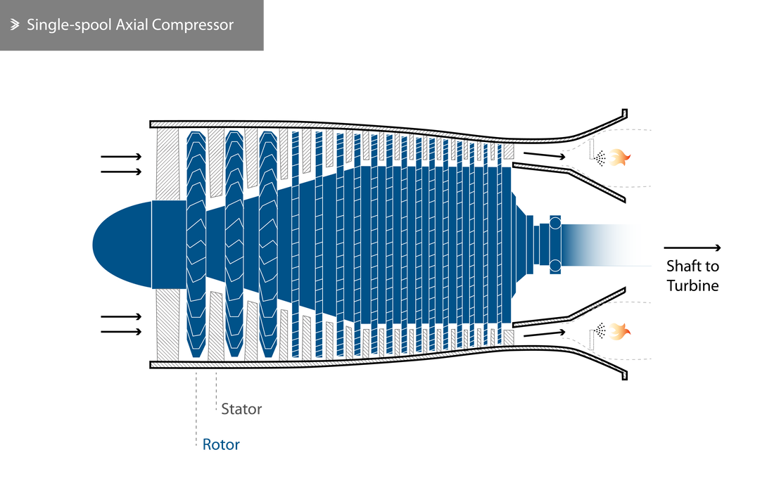
A single-spool compressor, such as the one shown below, consists of a single drum and multiple stators. The total number of stages is determined based on the desired pressure increase. A multi-spool compressor consists of two or three drums of rotors, each driven by a separate turbine segment at the best respective rotational speed, which subsequently results in the maximum possible compression ratio.
Even though two spools can be used for a simple engine (turbojet/no bypass), their implementation is much more suitable in dual flow engines. In these cases, the front part of the compressor is designed to initially compress a larger mass of air than the mass injected into the high-pressure (HP) compressor. The remainder of the flow is bypassed and, in many cases, merged with the core flow in the exhaust.
A fan may also be added at the front of a single- or multi-spool compressor. In triple-spool engines, the fan is driven by a dedicated segment of the turbine, making its shaft the low-pressure (LP) one. The fan effectively acts as a low-pressure compression stage towards its centre (slightly pressurising the air that goes into the core) and as a propeller that handles high mass flow rates towards the blade-mid and blade-tip region for the bypass flow. The smaller proportion of the flow, known as the core flow or hot air is passed through the intermediate-pressure (IP) and high-pressure (HP) compressor, the combustion chamber and the turbine.
During normal operation, the rotating assembly spins at sufficiently high speeds to ensure a steady intake. As the air passes through the rotors, it is accelerated and pushed towards the stators. Diffusion of the air between the stators and the rotors is the driving mechanism of the compression (i.e. acceleration of the flow by the rotors, which is subsequently disturbed by the stators forcing a given mass of air to pile-up against itself), but the stators also contribute by correcting the angle of the flow between rotors. A final row of stators is also usually employed to normalise the flow as this exits the compressor and prevent vortices or turbulence in the flow before it enters the combustion chamber. The evolution of pressure and velocity for a simple compressor can be seen below, but it is also worth mentioning that the increase in pressure and density is also accompanied by a steady increase in temperature too.
This repeated exchange of energy can be mathematically described using Bernoulli's equation which is:
This repeated exchange of energy can be mathematically described using Bernoulli's equation which is:
\[P_T=p+\frac{1}{2}\rho(u^2+v^2+w^2)\]
where:
\(P_T\) is the stagnation pressure
\(p\) is the static pressure
\(\rho\) is the air density
\(u\), \(v\) and \(w\) are the velocity components (radial, tangential and axial respectively)
The swirl added by the rotors contributes to an increase in the total energy carried by the flow as the angular momentum increases (associated with the \(\rho v^2/2\) term). The stator removes the swirl by converting its kinetic energy to internal energy, which is reflected by the rise of the value of \(p\).
From one stage to the next, the compression ratio is small and typically between 1.1 and 1.2. The reason why the pressure increase per stage is small is that both the amount of diffusion taking place and the degree of deflection of the flow should be kept relatively low to minimise losses due to flow separation and stall. The small but gradual increase of the pressure along multiple stages and a relatively steadier flow are two of the reasons why axial compressors perform better. For reference, the max speed in an axial compressor is Mach 0.9 and the flow is largely undisturbed, whereas in a centrifugal compressor it may be up to Mach 1.2 in a much more torturous path which includes a 90 degree bend before entering the combustion chamber.
To achieve a high compression rate, a large number of stages is required, but with adding more stages, the task of optimising the design for most efficient operation of each stage becomes more difficult. In some cases, automated flow control systems may be installed, but the use of multiple spools proves to be the most efficient alternative; an arrangement better suited for a wider range of operating conditions too. Engines like the Rolls-Royce Spey provided superior compression ratios at the time by using both a multi-spool compressor and automated flow control for the HP section.
Most modern civil jet engines have a fan at the front. In principle, the fan can be positioned either at the front or the rear of the engine, the former being far more common as operating such a large component in the cold part of the engine is more reliable. As with the LP/IP/HP compressors, the fan may also consist of one or more stages but in most double-spool engines and, currently, all triple-spool engines, the fan consists of a single stage.
3.6 Axial: Design & Manufacture
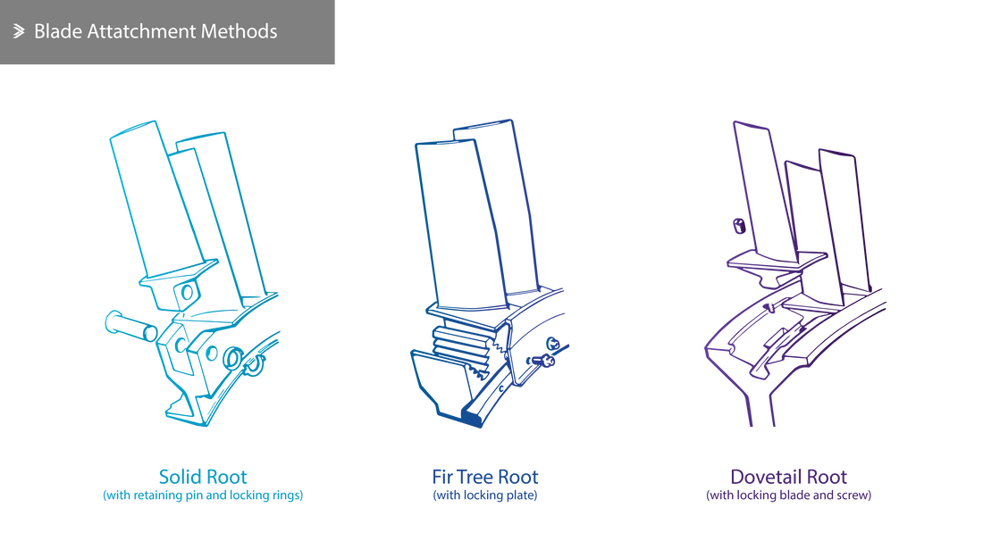
The most crucial part of the manufacturing of the compressor is the rotating assembly itself. The shaft of the rotors is supported by bearings and mounted on the stationary casing in such a way that allows for small alignment adjustments. The compressor casing consists of a number of cylindrical housings, some of which are split in half for ease of assembly and maintenance.
Rotors
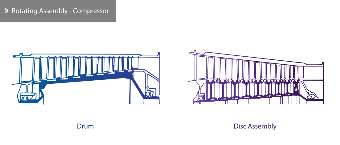
The rotating assembly may consist of a single drum or an assembly of individual discs or a combination of the two. In the case where a single drum is used, this is usually cast and then machined to size before the blades are assembled. Where individual discs are used, each row of rotors is secured on a dedicated disc, which is attached to the shaft directly. In drums, the region around the roots of the blades should sustain both the axial and circumferential loading which arises. In a disc assembly, on the other hand, the circumferential load is sustained by the discs, whereas the axial load is transferred to the spacers between discs.
Rotor Blades
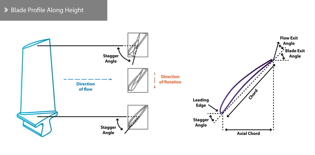
The blades are aerofoil-shaped, commonly designed and optimised to achieve a suitable pressure distribution along the length of the blade so that the airflow has a uniform axial velocity. The pressure at the blade tip is higher and this counteracts the centrifugal forces that the rotation of the blade induces on the flow. This is achieved by twisting the blade so that the stagger angle (or setting angle) changes to the optimum for that height. The total height of the blade also varies along the compressor with those at the front being the longest.
Stators
The stator vanes are also aerofoil-shaped and are mounted either directly on the casing of the compressor or onto rings that are mounted on the casing. The vanes are often assembled in smaller groups or with adjacent shroud rings that restrict the movement of the vane tips and reduce vibrations that might develop due to rapid changes in the airflow, especially at the front of the engine where the blades and vanes are longer. As would be expected, the vanes are also mounted in such a way that prevents their circumferential movements in the casing grooves.
Materials
Generally speaking, the material selection for the compressor is dictated by the need for excellent fatigue resistance, both in terms of mechanical and thermal loading. Good strength to weight ratio and good impact resistance are both essential properties, the latter in case of foreign object ingestion/damage (FOD).
Historically, titanium alloys, aluminium alloys and steel have been used to manufacture blades and vanes. In many cases, a combination of these or multiple alloys can be used depending on the position of the parts in the compressor and, subsequently, its operating temperature. Where the temperatures are sufficiently low, composites materials are now being used for critical components. The GE LEAP fan blades are a unique example of one-piece woven carbon fibre composite blades that offer very good strength for a reduced weight relative to titanium blades.
Similar combinations of materials are also used for the casing- the front part is often made of aluminium alloys (magnesium alloys had also been used in the past by some manufacturers), whereas the rear part is often made of steel.
3.7 Axial: Operating Conditions
In a multi-stage axial compressor, each stage or simply each pair of one rotor and one stator has its own flow characteristics that slightly differ from the rest. As a result, designing the most efficient compressor possible requires the optimisation of each particular stage. This is a reasonably easy task if one considers a simplified approach to the optimisation (i.e. in terms of airflow, pressure ratio or revolutions), but of course it is a particularly challenging design task due to the real conditions in the compressor.
Once the operating conditions exceed the design specifications, vortices tend to develop in the wake of the flow around the blades, leading to wider flow anomalies; this phenomenon is called stall or surge. These two terms are often used interchangeably but differ to the severity of the disruption to the flow. Stall refers to the flow disruption in one or a few stages, whereas surge reflects to flow disruption in all stages and, subsequently, to the compressor as a whole.
Compressor blades are designed to increase the pressure and velocity of the flow at a given rotational speed. If any, internal or external, factor disturbs the relationship between pressure, velocity and rotations, flow separation may occur leading to the creation of the vortices that were mentioned above. Reasons why this might occur include:
Generally speaking, if the reason why stall has occurred in one stage persists, this will propagate to the rest of the stages leading to a complete compressor surge. In minor or moderate stall cases, an unusual vibration might be felt or there might be a delay in the response as the engine is being sped up or slowed down. However, in exceptional circumstances the time it takes for a stall to turn to a complete surge can be very short.
It is worth noting that at low revolutions, minor surge is observed at the very first stages even if the engine is equipped with an automated flow control system. This kind of stall does not cause any damage to the compressor and generally goes unnoticed. More widespread stalling leads to a temperature increase in the compressor, felt vibrations and a thumping noise. Complete surge is also accompanied by temperature increase and louder thumping.
Once the operating conditions exceed the design specifications, vortices tend to develop in the wake of the flow around the blades, leading to wider flow anomalies; this phenomenon is called stall or surge. These two terms are often used interchangeably but differ to the severity of the disruption to the flow. Stall refers to the flow disruption in one or a few stages, whereas surge reflects to flow disruption in all stages and, subsequently, to the compressor as a whole.
Compressor blades are designed to increase the pressure and velocity of the flow at a given rotational speed. If any, internal or external, factor disturbs the relationship between pressure, velocity and rotations, flow separation may occur leading to the creation of the vortices that were mentioned above. Reasons why this might occur include:
- Reduction in air being sucked in due to icing
- Sudden change in the flow due to abrupt manoeuvre of the aircraft
- Sudden increase in the amount of fuel entering the combustion chamber
- Suction of a foreign body
- Damage of one or more blades (fatigue fracture, FOD, etc)
- Insufficient intake of air at very high altitudes
Generally speaking, if the reason why stall has occurred in one stage persists, this will propagate to the rest of the stages leading to a complete compressor surge. In minor or moderate stall cases, an unusual vibration might be felt or there might be a delay in the response as the engine is being sped up or slowed down. However, in exceptional circumstances the time it takes for a stall to turn to a complete surge can be very short.
It is worth noting that at low revolutions, minor surge is observed at the very first stages even if the engine is equipped with an automated flow control system. This kind of stall does not cause any damage to the compressor and generally goes unnoticed. More widespread stalling leads to a temperature increase in the compressor, felt vibrations and a thumping noise. Complete surge is also accompanied by temperature increase and louder thumping.
3.8 Axial: Surge
As defined above, surge occurs when the relationship between pressure, axial velocity and rotational velocity is disturbed, leading to anomalies in the flow throughout the compressor and the engine as a whole. Surge does not only affect the operation of a jet engine but can also cause serious or catastrophic damage to it.
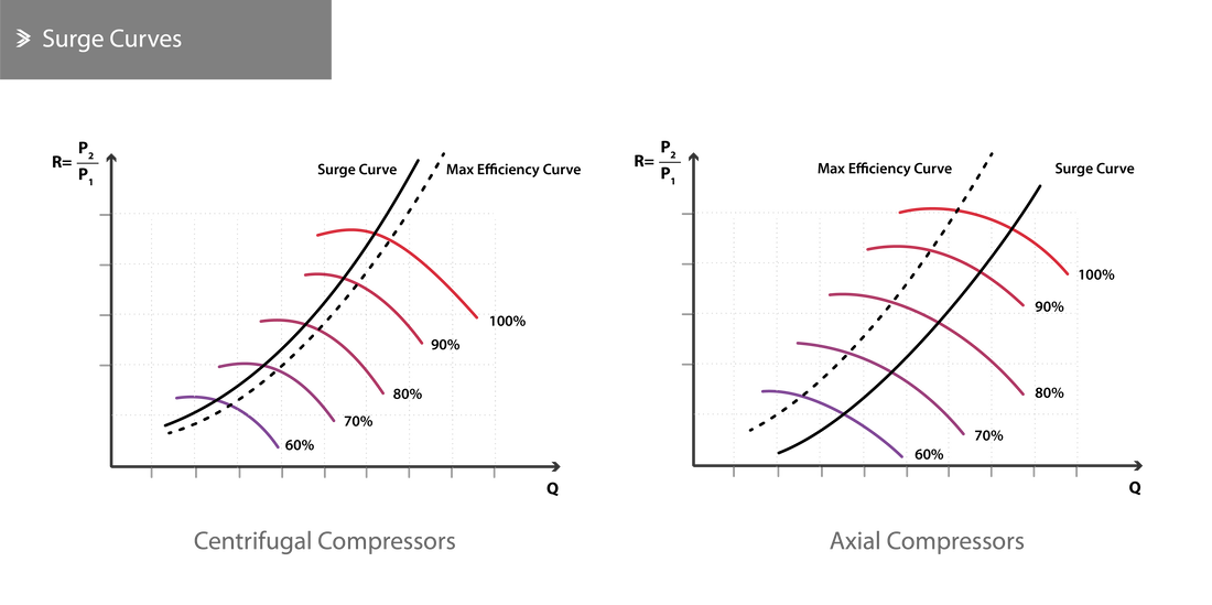
In order to avoid surge in an engine, its operation should be within the safe design limits. Defining the safe operational limits can be done by plotting the mass flow, \(Q\), against the pressure ratio. For a given rotational speed, a curve corresponds to the pressure ratio achieved for a given mass flow of air entering the engine. Drawing a line between all the points where the pressure ratio is the highest will lead to the maximum compression curve, corresponding to the most efficient operation of the compressor. In each of the operation curves, a surge point can also be identified and the line joining all such points is called the surge curve. This effectively indicates the lowest possible mass airflow in the compressor, whilst achieving normal operation.
Compressors are designed so that the operating pressures and mass flow rates include conservative safety margins to prevent surge in a wider range of conditions. By identifying the safest operation points in the curves above, the working line can be also drawn. The safety margin is the zone between the working line and the surge line.
In centrifugal compressors, the surge line falls to the left of the maximum efficiency line, whereas the opposite is the case for axial compressors. As operating the engine at higher pressure ratios leads to higher efficiency, centrifugal compressors do offer a slightly more stable operation than axial compressors. In reality, of course, axial compressors offer a range of operational benefits and through numerous stages and optimisation, compression ratios of up to 60:1.0 can be achieved, as is the case for GE's GE9X.
3.9 Axial: Stall
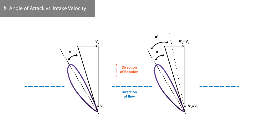
Stall in a compressor is often thought as very similar to wing stall, due to the similarity of the aerofoil profiles that aircraft wings and compressor blades have. Speaking of wings, it is widely known that stall occurs when the angle of attack exceeds a certain limit. When the velocity of the flow into a compressor changes rapidly a very similar situation arises. Assuming that the rotational speeds stay the same, a drop in the intake flow velocity would result in an increase of the angle of attack. As was discussed above, such a sudden drop can occur due to a number of reasons but sudden manoeuvres which cause a disturbance around the intake are one of the most common causes.
In the schematic above:
\(V_a\) is the axial (intake) velocity
\(V_r\) is the rotational velocity
\(\alpha\) is the angle of attack
It is also worth noting that as the flight altitude increases, the safe operational margins become narrower. Jet engines with afterburners, commonly found on fighter jets, face an additional risk of stall that can be a result of a combination of the fuel injection rate in the afterburner, the opening of the variable exhaust nozzle or the combustion efficiency, all of which can contribute to the creation of back-pressure.
Minor stall incidents are very common during the spooling up and shutting down stages of a journey and these don't normally cause any damage to the engine. As the engine throttle is pushed by the pilot, more fuel is injected in the combustion chamber to achieve the desired acceleration. If the jet engine was already operating near the stall limit, the addition of more fuel can momentarily push it into stall conditions. The injection of more fuels leads to a very brief but sharp increase in pressure in the chamber which slightly slows down the air leaving the compressor and, subsequently, entering the compressor too. Nowadays, most modern engines are equipped with more advanced fuel regulators and chambers that largely counteract this effect and maintain a sufficiently low risk of stall even during rapid acceleration.
Let's consider a double-spool engine that is being slowed down. As the throttled is pulled back, less fuel is injected in the combustion chamber and the high-pressure spool starts decelerating first due to its relatively smaller mass. This can lead to stall in the low-pressure stages for essentially the same reason as before.
Stall can also occur at high altitudes and without any sudden changes in the engine's speed. If ice crystals are present in the air, these will enter the engine and, upon reaching the hotter parts of the compressor, will evaporate. This rapid phase change is significant if one considers how thin the air is at high altitudes and can be the reason for stall in the high-pressure compressor. Operating any engine according to the manufacturer's specifications makes serious stall and surge incidents rare. Experienced operators are able to have a very good understanding of the engine's performance over a wide range of conditions and a quick response can overcome such issues without causing any damage.
3.10 Axial: Flow Control
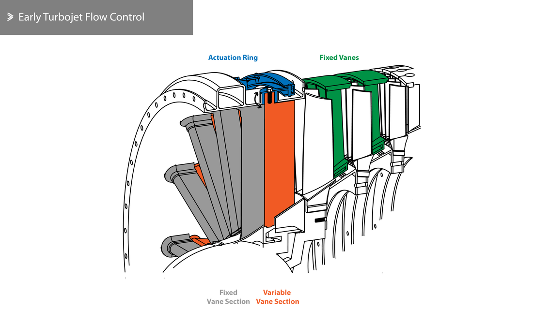
In many cases, it is desirable to install an automated flow control system to enable safe (surge-preventing) operation at a wider range of operating conditions. This typically includes an automatically controlled discharge (bleed) of compressed air from one of the intermediate stages either to the atmosphere or to the bypass flow (if a multi-spool arrangement exists as single-shaft turbofans are rare). It is also possible to use variable inlet guide vanes at the front of the compressor that adjust the angle of attack and prevent stall or surge at lower rotational speeds.
Bleeding air from the compressor can be achieved using a mechanically, hydraulically or pneumatically actuated valve that remains open when the compression ratio is low and gradually shuts as the rotational speed of the engine goes up. When the valve is open, the flow to the front stages is increased and reduced at the rear of the compressor. As such, the risk of stall in the first stages due to reduced flow is mitigated (as this has now increased) and the rear stages are no longer in danger of being chocked due to very high axial velocities (as the reduction in flow also leads to a reduction in velocity).
Bleeding air from the compressor can be achieved using a mechanically, hydraulically or pneumatically actuated valve that remains open when the compression ratio is low and gradually shuts as the rotational speed of the engine goes up. When the valve is open, the flow to the front stages is increased and reduced at the rear of the compressor. As such, the risk of stall in the first stages due to reduced flow is mitigated (as this has now increased) and the rear stages are no longer in danger of being chocked due to very high axial velocities (as the reduction in flow also leads to a reduction in velocity).
Back to Aeolus directory |
Next up: 4. Combustion |

