Back to Aeolus directory
4. Combustion Chambers
4.1 Combustion Process
4.2 Fuel Supply
4.3 Combustion Chamber Types
4.4 Combustion Chamber Efficiency
4.5 Materials
As the name suggests, the combustion chamber is designed to combust large quantities of fuel, mixed with even larger quantities of air which leaves the compressor. The combustion must be done in such a way that allows the air to expand and accelerate without causing instabilities over the entire range of operating conditions.
The amount of fuel injected in the combustion chamber is related to the desired temperature increase. However, this is limited by the thermal properties of the material used in the turbine and the exhaust nozzle, traditionally lying somewhere between 700°C and 1200°C. As the compressed air exiting the compressor is already at a higher temperature, the required temperature increase by the combustion chamber alone is usually between 500°C and 800°C.
The efficiency of the combustion process is an increasingly important area due to the constant increase in air traffic and the pollution that this causes. Over the last couple of decades, the price of jet fuel has also varied significantly, applying periodic pressure to develop leaner combustion and lower specific fuel consumption (SFC) engines. In terms of \(CO_2\), jet engines are rather efficient, as the emissions per passenger and per kilometre travelled are notably lower than that for a single person driving a car. For long-haul travel, the emissions of aircraft are comparable to those of a bus per passenger and per kilometre travelled. However, other emissions associated with the high altitude, notably nitrogen oxides, \(NOx\), do contribute to the harmful effects including the disturbance of atmospheric ozone. The continuous optimisation over the last 50 years and availability of newer or improved materials have been successful in delivering engines with an ever decreasing environmental impact.
4.1 Combustion Process
Compressed air enters the combustion chamber with a typical speed of 150 m/s, which is, in fact, too high for effective combustion. The first step is to slow down the stream of compressed air and, subsequently, increase its static pressure. Due to the flame speed of jet fuel, a reduced flow velocity of even 80 ft/s (24.4 m/s) would extinguish any flame. Hence the need for a combustion region with air flowing at a much lower axial velocity, so that combustion is sustained over a wide range of operating conditions.
In normal operation, the air-to-fuel (AF) ratio varies between 45:1 and 130:1. Kerosene-based fuels are most efficiently burned at an AF ratio of around 15:1 and as such, only a fraction of the air entering the combustion chamber actually takes part in the combustion process. This is referred to as the primary combustion zone.
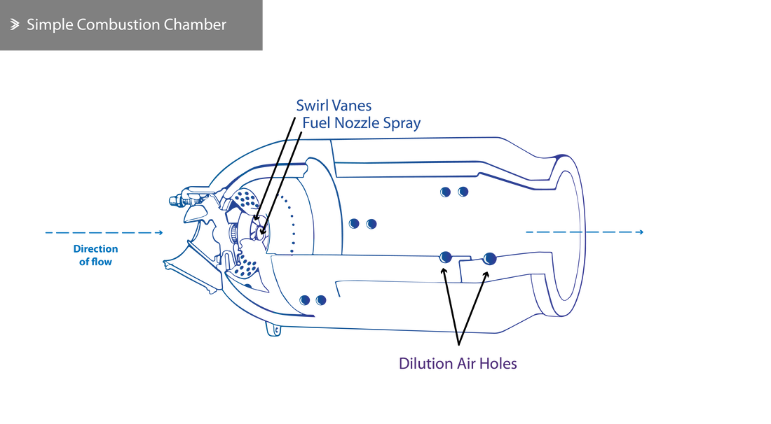
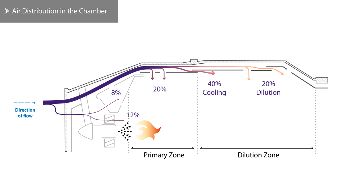
Around 20% of the air mass is guided directly towards the core of the chamber. At the point of entry, swirl vanes and a perforated flare force the incoming air to whirl, promoting better air circulation and mixing through the chamber. The remaining 80% of the air mass is fed between the combustion chamber lining and its casing with a significant cooling function.
The liner has a number of openings that allow up to 20% of the main flow to enter the primary combustion zone. The air that went through the swirl vanes and these openings forms a small recirculation zone with relatively slow flow speeds. This recirculation also accelerates the combustion of the injected fuel droplets, offering a rapid temperature rise up to the stabilised combustion temperature.
The temperature of the combustion products by the end of the primary zone can reach 1800-2000°C and needs to be cooled down before entering the turbine. To achieve this, the unused air so far (amounting to around 60%) is gradually introduced in the chamber. One could say that around half of that secondary flow is used to cool down the combustion gasses and the other half to cool down the combustion lining and casing. It is also worth mentioning that combustion should be completed before the coolest stream of air at the end of the combustor is introduced, otherwise, the combustion efficiency will drop sharply due to the low temperature.
Initiating combustion is usually achieved using spark plugs at startup. Once air is flowing through the core and the temperature rises, the combustion is self-sustaining and the plugs are no longer required. Combustion chamber design can vary greatly from one engine to the next in a number of ways such as the way fuel is injected, how cooling is realised and how the flow is managed.
Initiating combustion is usually achieved using spark plugs at startup. Once air is flowing through the core and the temperature rises, the combustion is self-sustaining and the plugs are no longer required. Combustion chamber design can vary greatly from one engine to the next in a number of ways such as the way fuel is injected, how cooling is realised and how the flow is managed.
4.2 Fuel Supply
Introducing the fuel into the combustion area can be realised in different ways that are based on one of the two principles; spraying it in the form of fine particles in the swirled stream of air in the primary combustion zone or vaporising the fuel before this enters the combustion area.
Pre-vaporisation is rarely used and most engines are equipped with spraying nozzles. For this reason, such combustion chambers will not be discussed in detail; their structure differs in the sense that swirl vanes are not required, whilst hook-like metal tubes are used to deliver the fuel. The open end of the tubes is facing against the flow of air and the rise in temperature towards the ends of the tubes is what drives the vaporisation process. The gaseous fuel exits the tubes and combusts in the chamber, as before.
Pre-vaporisation is rarely used and most engines are equipped with spraying nozzles. For this reason, such combustion chambers will not be discussed in detail; their structure differs in the sense that swirl vanes are not required, whilst hook-like metal tubes are used to deliver the fuel. The open end of the tubes is facing against the flow of air and the rise in temperature towards the ends of the tubes is what drives the vaporisation process. The gaseous fuel exits the tubes and combusts in the chamber, as before.
Fuel Injection
Fuel injectors are designed in such a way that makes the most of the fuel's pressure to finely disperse it or vaporise it, which will aid its quick and complete combustion. In contrast to piston engines, jet engine combustion chambers have to deal with very high flow rates and velocities, making their design more demanding than the basic principle it's based on would suggest.
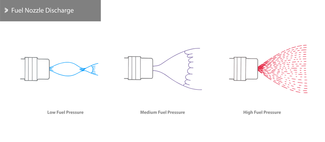
Two of the most common ways to finely disperse the fuel are to force it through either a finely perforated disc or through a small gap between two rings to achieve some swirl, dispersion or evaporation. A key prerequisite for this is to supply the fuel under high pressure which, in some cases, also goes through a pre-injection chamber with fins that add a swirl to the flow of the fuel. Under a low injection pressure, the fuel would come out as a continuous, bubble-shaped flow. As the pressure increases, the boundary layer of the flow starts breaking up to form what is described as a 'tulip'. Finally, at full operational pressure, the fuel breaks up to much smaller segments, effectively forming a finely atomised spray zone.
Two of the most common ways to finely disperse the fuel are to force it through either a finely perforated disc or through a small gap between two rings to achieve some swirl, dispersion or evaporation. A key prerequisite for this is to supply the fuel under high pressure which, in some cases, also goes through a pre-injection chamber with fins that add a swirl to the flow of the fuel. Under a low injection pressure, the fuel would come out as a continuous, bubble-shaped flow. As the pressure increases, the boundary layer of the flow starts breaking up to form what is described as a 'tulip'. Finally, at full operational pressure, the fuel breaks up to much smaller segments, effectively forming a finely atomised spray zone.
4.3 Combustion Chamber Types
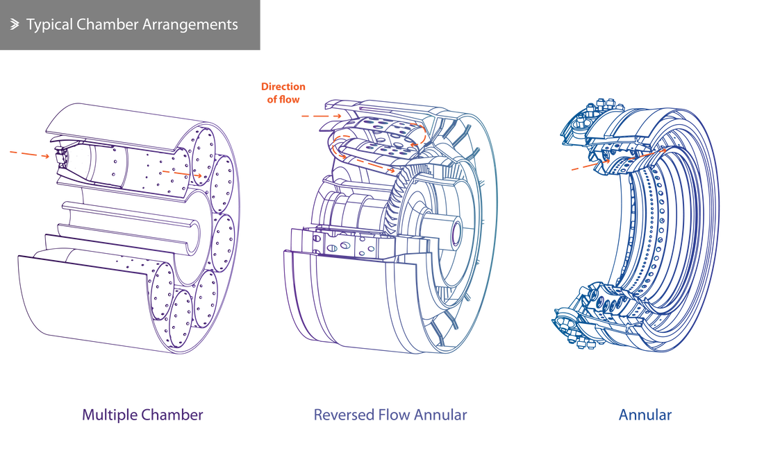
Even though three main types of combustion chambers can be identified (the multiple-chamber, the tubo-annular and the annular combustion chamber), it is worth noting that the majority of modern jet engines including high-bypass engines have annular combustion chambers.
Multiple-Chamber Combustion Chamber
The multiple-chamber design can be found in jet engines with a centrifugal compressor and old axial compressors. It is effectively an improved version of Frank Whittle's combustion chamber that featured reversed flow which, however, led to a considerable pressure loss.
Cylindrical chambers are arranged around the engine shaft and the air is delivered from the compressor via ducts. These individual chambers are not entirely separated; short tubes connect them to ensure the air pressure is distributed evenly and so that the flame can propagate to all chambers, as ignition first takes place in a single or two chambers.
Cylindrical chambers are arranged around the engine shaft and the air is delivered from the compressor via ducts. These individual chambers are not entirely separated; short tubes connect them to ensure the air pressure is distributed evenly and so that the flame can propagate to all chambers, as ignition first takes place in a single or two chambers.
Tubo-Annular Combustion Chamber
The tubo-annular combustion chamber is a combination of the multiple-chamber and the annular designs. It also consists of multiple, individual chambers that are all placed within the same casing. The overall principle of design is very similar to that described already and does not lead to any significant maintenance or performance gains.
Annular Combustion Chamber
The annular combustor consists of a single ring-shaped 'chamber' between an inner and outer casing. Due to the continuity of the flow around the rings, flame propagation takes place with more ease. The main advantage of an annular combustor is that for the same given power requirement, it can take up as low as 75% of the space required for a tubo-annular combustion chamber. When compared to a tubo-annular combustion chamber the surface area exposed to very high temperatures is much lower, meaning that the amount of air used to cool down an annular combustor is about 15% less. Furthermore, it delivers the most even load distribution to the first stage of the turbine compared to the other arrangements.
The reduction in the amount of cooling air that is required leads to a rise in the combustion efficiency as all the fuel can be burned completely, eliminating the carbon monoxide to be released into the atmosphere. All modern high-bypass jet engines have annular combustors.
The reduction in the amount of cooling air that is required leads to a rise in the combustion efficiency as all the fuel can be burned completely, eliminating the carbon monoxide to be released into the atmosphere. All modern high-bypass jet engines have annular combustors.
4.4 Combustion Chamber Efficiency
As mentioned earlier, the main design challenge around the combustion chamber is to ensure efficient combustion across a range of operating conditions without significant pressure loss. Furthermore, it is important to have the capability to re-ignite the fuel on the rare occasion of it being unintentionally extinguished. Therefore, it becomes apparent that even though the fuel injectors and spark plugs are simple in their operation, their reliability is of paramount importance.
Theoretically speaking, combustion can be assumed to be carried out with no pressure loss. However, since that's not entirely possible, it's important to keep the losses to a minimum. The pressure loss mostly occurs due to the desire to introduce the swirl and, subsequently, efficient air-fuel mixing. This drop is typically around 5% to 10%.
Theoretically speaking, combustion can be assumed to be carried out with no pressure loss. However, since that's not entirely possible, it's important to keep the losses to a minimum. The pressure loss mostly occurs due to the desire to introduce the swirl and, subsequently, efficient air-fuel mixing. This drop is typically around 5% to 10%.
Combustion Efficiency
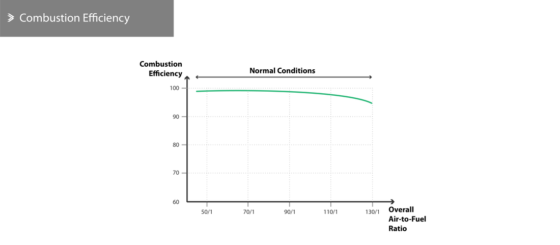
Combustion efficiency of a modern engine at sea level (i.e. during take-off for most locations) is 100% and reduces to about 98% during cruise. The efficiency depends on the pressure of the air, the stabilised temperature and the air-to-fuel ratio, as shown below.
Combustion Stability
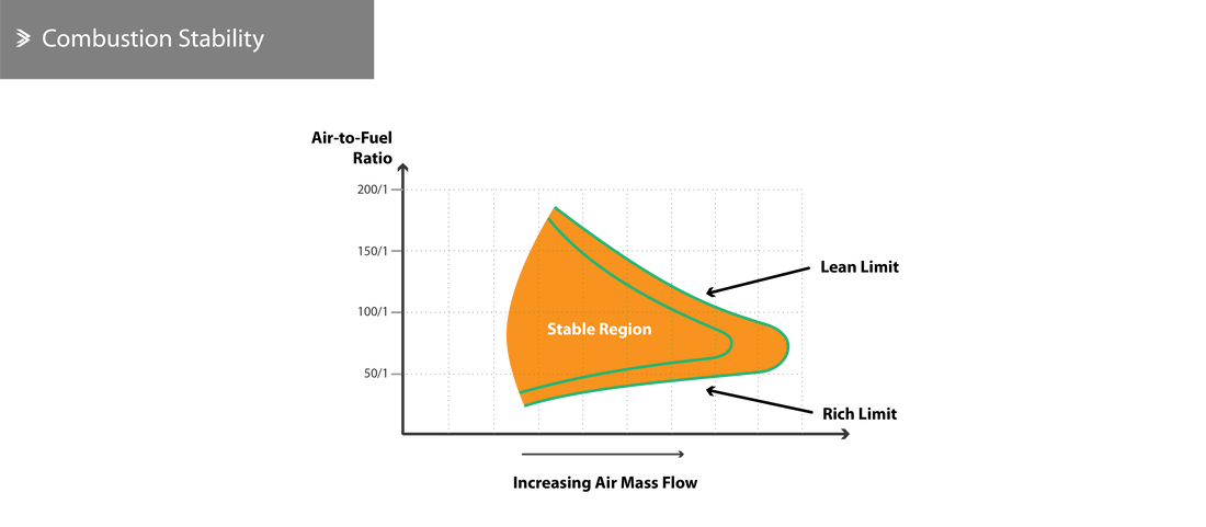
Combustion stability refers to the normal combustion conditions and the chamber's ability to sustain a stable flame over a range of conditions. For each combustion chamber design, there are operational limits to the air-to-fuel ratio that define a fuel-lean and fuel-rich limit. It is possible for the flame in the chamber to be extinguished during periods of quick ascend or descend where the flow of air is high and the fuel injection rate is low.
The stable flame region becomes narrower as the airspeed increases- past a certain point the flame will be extinguished regardless of the air-to-fuel ratio. The combustion process itself has lean (weak) and rich limits that can be visualised as a curve within the stable region.
The stable flame region becomes narrower as the airspeed increases- past a certain point the flame will be extinguished regardless of the air-to-fuel ratio. The combustion process itself has lean (weak) and rich limits that can be visualised as a curve within the stable region.
Carbon Formation
Jet engines with high compression ratios produce visible smoke during take-off which indicates the formation of carbon in the primary combustion zone. The underlying cause of this, is the presence of a fuel-rich mixture, relatively low swirl, high temperatures and high pressures. The presence of smoke is also an indication of a drop in the combustion efficiency which only amounts to 0.2-0.3%.
4.5 Materials
There is an inherent and apparent need for materials with high-temperature resistance for the combustion chamber liner, inner casing and inner components. Even though material with excellent thermal properties are widely used, their properties alone would not suffice and their use relies on effective cooling throughout their service lives. The most highly optimised combustion chamber designs deliver a thin layer of cooling air over the inner lining, such that the flame does not directly come into contact with the parts.
The mid and outer casings of the chamber should also show excellent thermal and mechanical fatigue properties; the former to combat the nucleation of cracks due to the high thermal gradients that develop and the latter due to the vibration-induced cyclic loading.
The linings are often made of nickel alloys, most containing both nickel and iron, among other elements. Nickel does offer exceptional thermal and strength characteristics but is also very dense and its use is typically limited to parts where it's absolutely necessary. The outer casings can be manufactured from steel.
Back to Aeolus directory |
Next up: 5. Turbines |

