
Back to Aeolus directory
8. Engine Performance
8.1 Introduction
8.2 Key Relationships & Functions
8.3 Thrust, Horsepower & External Factors
8.4 Thrust Distribution
8.5 Propulsive Efficiency
8.6 Specific Fuel Consumption
8.1 Introduction
The most characteristic property of a jet engine depends on its type; broadly speaking, that will be the thrust for turbofans and turbojets and shaft horsepower for turboprops. Thrust is measured in pounds (lb) or newtons (N), whilst shaft power can be measured in horsepower (hp) or, more commonly, Watts (W).
As has been discussed previously, the thrust or power of a jet engine depends on the mass of air entering the engine and the acceleration that is achieved by the time it leaves the exhaust. However, both properties are also inherently dependent on the aircraft velocity, the altitude and the atmospheric conditions (specifically the temperature).
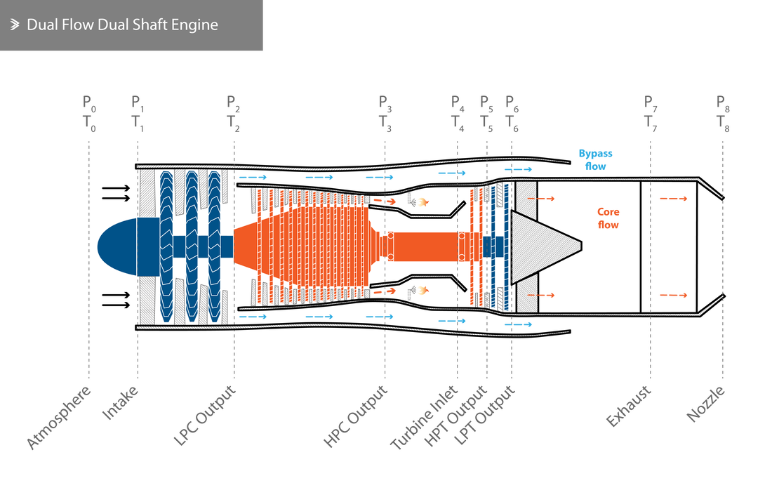
From a design point of view, it is desirable to achieve the highest thrust-to-weight ratio with the minimum possible specific fuel consumption. Even though the fundamental principles of jet propulsion haven't significantly evolved over the last few decades, jet engines nowadays are lighter, more reliable, burn less fuel for a given thrust output and produce less harmful emissions. In this section, we look into the relationships that govern some key performance characteristics of jet engines. In order to do that, the pressure and temperature state at multiple points across the engine is monitored or calculated.
As has been discussed previously, the thrust or power of a jet engine depends on the mass of air entering the engine and the acceleration that is achieved by the time it leaves the exhaust. However, both properties are also inherently dependent on the aircraft velocity, the altitude and the atmospheric conditions (specifically the temperature).
From a design point of view, it is desirable to achieve the highest thrust-to-weight ratio with the minimum possible specific fuel consumption. Even though the fundamental principles of jet propulsion haven't significantly evolved over the last few decades, jet engines nowadays are lighter, more reliable, burn less fuel for a given thrust output and produce less harmful emissions. In this section, we look into the relationships that govern some key performance characteristics of jet engines. In order to do that, the pressure and temperature state at multiple points across the engine is monitored or calculated.
8.2 Key Relationships & Functions
As mentioned above, the key characteristics that will be discussed are related to the thrust (or shaft power), other measures of power in the engine, the operational efficiency, the specific fuel consumption and the way some of these are affected by parameters such as the aircraft velocity and altitude, shaft revolutions and air temperature. The following variables will be used:
\(T\) is the propulsive thrust (commonly in lbf or N)
\(\dot M_a\) is the mass flow rate of air
\(M_a\) is the mass of air
\(\dot M_f\) is the mass flow rate of fuel
\(M_f\) is the mass of fuel
\(\dot M_j\) is the mass flow rate of the exhaust gases
\(M_j\) is the mass of exhaust gases
\(V\) is the aircraft velocity (commonly in knots, we will use km/h)
\(V_j\) is the exhaust velocity (m/s)
\(A\) is the nozzle cross-sectional area
\(P_8\) is the static pressure across the nozzle (kPa)
\(P_0\) is the atmospheric pressure (kPa)
\(C_P\) is the specific heat capacity of the fuel (commonly in kJ/kg °C or BTU/lb °F)
\(b\) is the thrust specific fuel consumption (commonly in lb/lbf·hr or g/kN·s for turbofans/turbojets and lb/hp*hr or g/W·s for turboprops)
Thrust
Going back to the basic principles, the thrust is defined as:
\[T=\dot M (V_j-V)\]
which, for choked nozzle conditions, becomes:
\[T=\dot M (V_j-V)+(P_8-P_0)A\]
Power
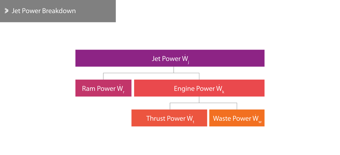
Many different measures of power can be related to a jet engine, some of which are interconnected. Primarily, jet power is defined as the power related to the kinetic energy of the exhaust gases or mathematically:
\[\dot W_j=\frac{1}{2}\dot M_j\cdot V_j^2\]
On the opposite end of the engine, the atmospheric air going into the engine also possesses some kinetic energy and it's potential to do work is referred to as ram power. This can be defined as:
\[\dot W_r=\frac{1}{2}\dot M_a\cdot V^2\]
The engine power is also very important as this refers to the power available for the propulsion of the aircraft. This is the subtraction of the ram power from the jet power:
\[\dot W_k=\dot W_j-\dot W_r=\frac{1}{2}\dot M\cdot V_j^2-\frac{1}{2}\dot M_a\cdot V^2\]
In certain cases, it might be allowable to assume that the mass of air going into the engine is the same as the mass of air leaving the exhaust (even though they differ slightly if we take into account bleed/cooling air), such that \(\dot M\approx \dot M_a\), then the relationship can be simplified to:
\[\dot W_k=\frac{1}{2}\dot M(V_j^2-V^2)\]
If we multiply the brackets out, the expression for thrust appears, so engine power can be expressed as:
\[\dot W_k=\frac{1}{2}T(V_j+V)\]
Thrust power is a fraction of engine power that is actually used for the movement of the aircraft and is simply the product of the thrust and the aircraft velocity, such that:
\[\dot W_t=T\cdot V \Leftrightarrow \dot W_t=\dot M(V_j-V)V\]
The remainder of the engine power that isn't converted to thrust power is called waste power. A simple subtraction leads to:
\[\dot W_w=\dot W_k-\dot W_t=\frac{1}{2}T(V_j+V)-T\cdot V \Leftrightarrow \dot W_w=\frac{1}{2}T(V_j-V)\]
Finally, the only power that isn't a subset of any of the above is the fuel power which is effectively the energy of the fuel being consumed and is equal to:
\[\dot W_f=\dot M_f\cdot C_P\cdot \Delta T\]
Bear in mind that the value of \(C_P\) varies with temperature. Another useful formula uses the heat of combustion, which in the form of the Higher Heating Value (HHV) or Lower Heating Value (LHV) can be commonly found in fuel property lists.
\[\dot W_f=\dot M_f\cdot~\textrm{HHV}\]
Efficiency
Similarly, efficiency can be measured and expressed in many different ways that related to different components of the engine's performance. Firstly, we have the engine (kinetic) thermal efficiency which can be defined as:
\[\eta_\theta=\frac{\dot W_k}{\dot W_f}\]
The thrust thermal efficiency is:
\[\eta_{\theta-t}=\frac{\dot W_t}{\dot W_f}\]
And the propulsive efficiency is defined as:
\[\eta_{prop}=\frac{\dot W_t}{\dot W_k}=\frac{T\cdot V}{\frac{1}{2}T(V_j+V)}\]
which can be re-arranged to:
\[\eta_{prop}=\frac{2V}{V_j+V}\Leftrightarrow \eta_{prop}=\frac{2}{\frac{V_j}{V}+1}\]
It is worth noting that the thrust thermal efficiency is, in fact, the product of the engine thermal efficiency and the propulsive efficiency and as such we can also refer to it as the overall thermal efficiency.
\[\eta_{\theta-t}=\eta_\theta\cdot \eta_{prop}\]
Specific Fuel Consumption
For turbofans and turbojets, the TSFC is simply expressed as:
\[b=\frac{\textrm{Fuel consumption rate per hour}}{\textrm{Thrust}}=\frac{kg/hr}{kN}=\frac{kg}{kN\cdot hr}\]
For turboprops:
\[b=\frac{\textrm{Fuel consumption rate per hour}}{\textrm{Power}}=\frac{kg/hr}{W}=\frac{kg}{W\cdot hr}\]
Specific Engine Weight
For turbofans and turbojets, the specific engine weight is expressed as:
\[b=\frac{\textrm{Engine Weight}}{\textrm{Maximum Thrust}}\]
Example
For a particular engine in certain conditions, the following information is provided to calculate the power and efficiency of the engine:
- Aircraft velocity \(V=960~\textrm{km/h}=266.7~\textrm{m/s}\)
- Exhaust gas velocity \(V_j=585~\textrm{m/s}\)
- Mass rate of exhaust gases \(\dot M_j=27~\textrm{kg/s}\)
- Fuel consumption rate \(\dot M_f=0.35~\textrm{kg/s}\)
- Heat of combustion (HHV) of Jet A-1 \(\textrm{HHV}=43.2~\textrm{MJ/kg}\)
We can now calculate the following:
\[\dot W_j=\frac{1}{2}\dot M\cdot V_j^2=\frac{1}{2}\cdot \dot M_j\cdot V_j^2=\frac{1}{2}\cdot 27\cdot 585^2=4.62\cdot 10^6~\textrm{W}=4.62~\textrm{MW}\]
\[\dot W_r=\frac{1}{2}\cdot \dot M_j\cdot V^2=\frac{1}{2}\cdot 27\cdot 266.7^2=960240.02~\textrm{W}=960.24~\textrm{kW}\]
\[\dot W_k=\dot W_j-\dot W_r=4.62-0.96\approx 3.66~\textrm{MW}\]
\[\dot W_t=\dot M(V_j-V)V=27\cdot (585-266.7)\cdot 266.7=2.2920\cdot 10^6~\textrm{Q}\approx 2.29~\textrm{MW}\]
\[\dot W_w=\dot W_k-\dot W_t=3.66-2.29=1.37~\textrm{MW}\]
\[\dot W_f=\dot M_f\cdot HHV=0.35\cdot 43.24=15.13~\textrm{MW}\]
\[T=\dot M(V_j-V)=27\cdot (585-266.7)=8594.1~\textrm{N}\approx 8.59~\textrm{kN}\]
\[\eta_\theta=\frac{\dot W_k}{\dot W_f}=\frac{3.66}{15.13}=0.242~\textrm{(24.2%)}\]
\[\eta_{\theta-t}=\frac{\dot W_t}{\dot W_f}=\frac{2.29}{15.19}=0.151~\textrm{(15.1%)}\]
\[\eta_{prop}=\frac{\dot W_t}{\dot W_k}={2.29}{3.66}=0.626~\textrm{(62.6%)}\]
8.3 Thrust, Horsepower & External Factors
It should be well understood by now that the principal performance metric for turbojets and turbofans is the thrust that they produce, whereas for turboprops the shaft power that drives the propeller is primarily used instead. At the end of the day, the propeller does produce thrust in a way that is more efficient for slower aircraft velocities.
To compare the deliverable thrust from a turboprop and a turbofan, we need to be able to convert between the two:
To compare the deliverable thrust from a turboprop and a turbofan, we need to be able to convert between the two:
\[\textrm{Thrust Horsepower (THP)}~W=T\cdot V\]
to covert between different units. If data is expressed in imperial units (lbf for thrust, mph for the aircraft velocity and hp for the power), the formula can be expressed as:
\[\textrm{Thrust Horsepower (THP)}~W=\frac{T\cdot V}{375}\]
If the velocity is provided in knots (where 1kn=1.15mph):
\[\textrm{Thrust Horsepower (THP)}~W=\frac{T\cdot V}{325}\]
Example
For a turbofan delivering 35 kN whilst travelling at 950 km/h (263.9 m/s), the thrust horsepower is:
\[W=35\cdot 263.9=9236.5~\textrm{kW}\approx 12386~\textrm{hp}\]
In order for a turbofan with propulsive efficiency of \(\eta_{prop}=0.55\) to deliver the same thrust, the following thrust horsepower would be required:
\[0.55\times W=35\cdot 263.9 \Leftrightarrow W=16793.6~\textrm{kW}\approx 22521~\textrm{hp} \]
Gross Thrust
We have already discussed the expressions for thrust both under normal and under chocked conditions. If the engine is fixed to the ground for a static test, both these conditions can be simplified to:
\[T=\dot M\cdot V_j\]
for normal operation and:
\[T=\dot M\cdot V_j+(P-P_0)A\]
for choked conditions. This, 'total' thrust during static conditions is often referred to as gross thrust and the component that has been omitted \(\dot M\cdot V\) is called momentum drag. For a chocked exhaust, then the fraction of the gross thrust that is attributed to the exhaust gases is called momentum thrust and the fraction that is attributed to the pressure difference is called the pressure thrust. To summarise mathematically:
Gross Thrust \(\dot M\cdot V_j+(P-P_0)A\)
Momentum Thrust \(\dot M\cdot V_j\)
Pressure Thrust \((P-P_0)A\)
Momentum Drag \(\dot M\cdot V\)
Net Thrust \(\dot M(V_j-V)+(P-P_0)A\)
Momentum Thrust \(\dot M\cdot V_j\)
Pressure Thrust \((P-P_0)A\)
Momentum Drag \(\dot M\cdot V\)
Net Thrust \(\dot M(V_j-V)+(P-P_0)A\)
From the last equation, it can be seen that the net thrust can be increased by either increasing the mass of the exhaust gases (i.e. through water injection) or by increasing the exhaust gas velocity (through afterburning).
Afterburning
During take-off, the aircraft speed is relatively low and, as such, so is the momentum drag, which results in the momentum thrust being almost equal to the gross thrust. Using an afterburner during take-off can lead to a thrust increase of around 30% for a turbojet and even higher for low-bypass turbofans.
During cruising, the thrust increase associated with the use of an afterburner is even more significant because the momentum drag is the same whether the afterburner is engaged or not. In fact, due to the ram effect, the intake air is better utilised in this case.
During cruising, the thrust increase associated with the use of an afterburner is even more significant because the momentum drag is the same whether the afterburner is engaged or not. In fact, due to the ram effect, the intake air is better utilised in this case.
Example
An aircraft is cruising at 950 km/h (263.9 m/s) and for every kilogram of air entering per second, the momentum drag developing can be quantified as:
\[1\cdot 263.9=263.9~\textrm{N}\]
If we assume that the gross thrust per kilogram of air is 762.4 N, then the net thrust is:
\[762.4-263.9=498.5~\textrm{N}\]
However, if we assume a 30% thrust increase due to the use of an afterburner, the gross thrust becomes:
\[1.3\cdot 77.5=991.1~\textrm{N}\]
But for the given velocity, the updated net thrust is:
\[991.1-263.9=727.2~\textrm{lb}\]
This means that the thrust increase, in this case, was in fact:
\[\frac{727.2}{498.5}\approx 1.46\]
i.e 46%, which does, of course, comes with an increased total and specific fuel consumption.
Aircraft Speed
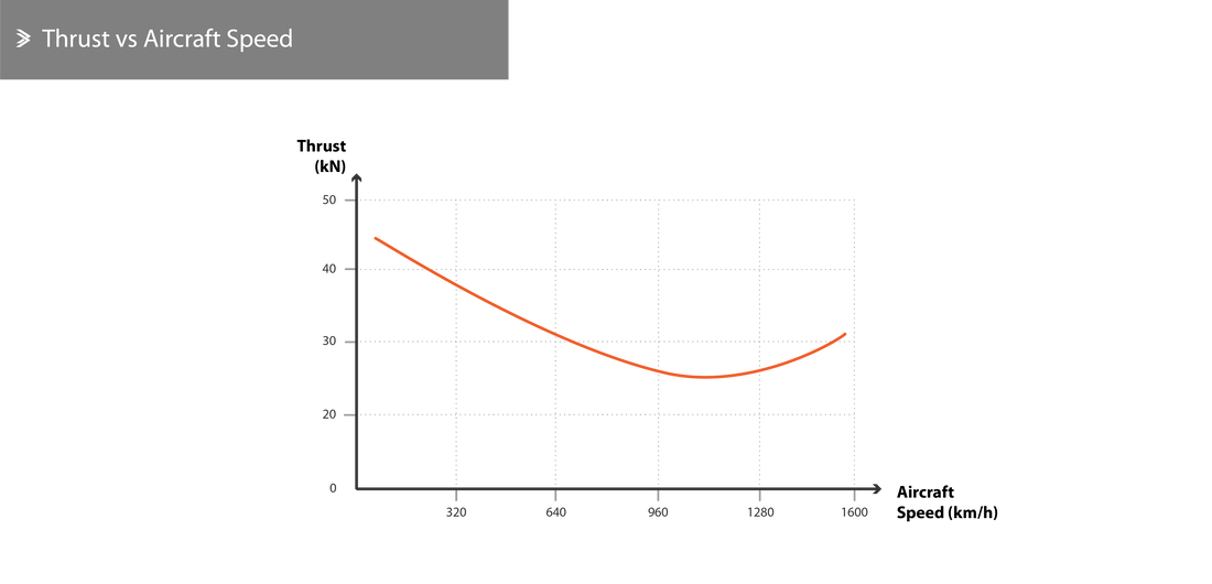
If we consider one of the fundamental thrust equations, \(T=\dot M(V_j-V)\), and assume that the velocity of the exhaust gases is constant, one could conclude that as the aircraft velocity increases, so does the momentum drag, ultimately leading to a reduction in net thrust. Of course, this is also why the maximum attainable thrust is recorded under static conditions.
However, this is true for relatively lower aircraft velocities. As the aircraft velocity increases, the pressure at the intake also increases. For a well-designed intake and engine, in general, this will result in an increase in the mass of air being taken in, an increase in the velocity of the exhaust gases and an increase in net thrust. This is called the ram effect and can be quantified by the ratio of the total pressure of air going into the compressor over the static pressure of air in the intake.
However, this is true for relatively lower aircraft velocities. As the aircraft velocity increases, the pressure at the intake also increases. For a well-designed intake and engine, in general, this will result in an increase in the mass of air being taken in, an increase in the velocity of the exhaust gases and an increase in net thrust. This is called the ram effect and can be quantified by the ratio of the total pressure of air going into the compressor over the static pressure of air in the intake.
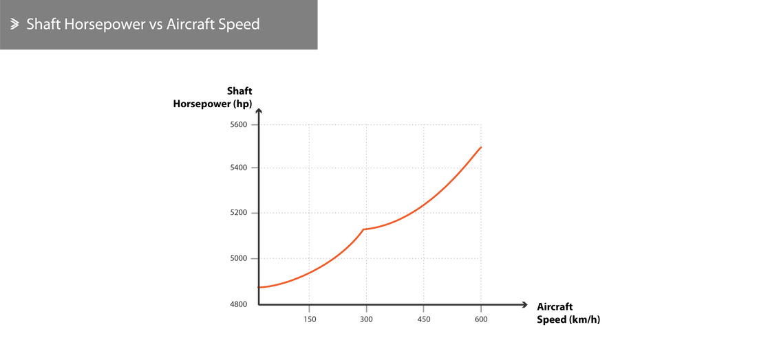
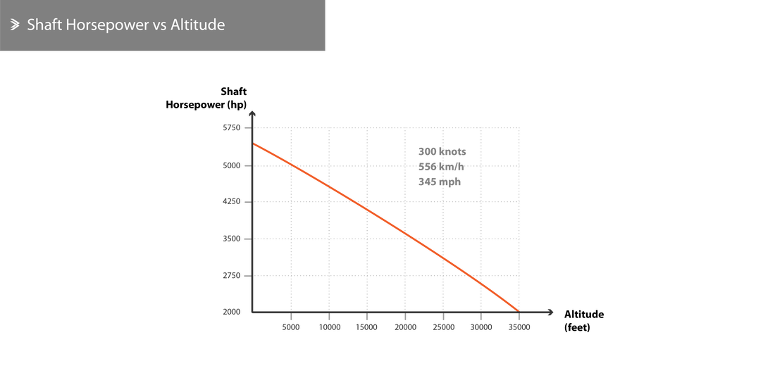
For turboprops, the relationship is a bit different as the thrust due to exhaust gases reduces as the aircraft velocity increases. The thrust generated by the propeller also decreases with increasing aircraft velocity, even though the shaft horsepower increases.
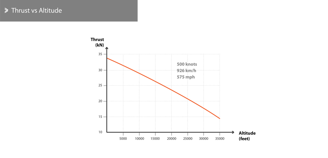
Altitude
As an aircraft climbs to higher altitudes, both the temperature and pressure of the air drops. The drop in pressure primarily equates to a drop in the specific weight of the air and subsequently, of the mass of air entering the engine for a given number of revolutions per minute. Modern engines are equipped with an automated fuel flow control system that reduced the amount of fuel entering the combustion chamber which ultimately leads to a reduction in net thrust.
On the other hand, the drop in temperature increases the density of the air which somewhat counteracts the effects of the pressure drop. Having said that, at an altitude between 35000 ft and 65000 ft, the temperature is fairly constant (around -56.5°C), meaning that the change in pressure has the exact effect that was described above.
On the other hand, the drop in temperature increases the density of the air which somewhat counteracts the effects of the pressure drop. Having said that, at an altitude between 35000 ft and 65000 ft, the temperature is fairly constant (around -56.5°C), meaning that the change in pressure has the exact effect that was described above.
Revolutions
This is a rather simple relationship as an increase in rotational speed of the shaft(s) leads to an increase in air being suck into the engine and subsequently an increase in the fuel being pumped in the combustion chamber. This leads to an increase in both net thrust (for turbofans and turbojets) and shaft horsepower (for turboprops), assuming any of the operational limitations have not been reached.
Climate
In colder climates, whether this is due to seasonality or due to flying near the poles, the consistently lower temperatures are associated with a slight increase in air density. For this reason, the mass of air entering the engine at any given revolution is slightly higher, meaning that the thrust is also slightly higher. However, these conditions also mean that the compressor needs slightly more power to run. If the goal was to maintain the same shaft rpm, more fuel would have to be burned to maintain that, but modern systems usually adjust the supply in colder environments so that the revolutions are in fact a little bit lower. Coupled with the increased air density this has no effect on the thrust.
To elaborate on that and better explain the operation of the automated system; the fuel system is programmed to adjust the flow of fuel in order to maintain the same rpm across the range of external conditions. As the temperature drops, this adjustment will lead to an increase in thrust until a critical value of air pressure at the exit of the compressor is reached. Past this point, the flow of fuel is adjusted so that the pressure does not exceed the critical value, irrespective of rpm. From the schematic below, it can be seen that the ratio between HP and LP rpm reduces as the temperature also reduces. Provisions are also in place to avoid extremely high revolutions in an attempt to balance out the performance of the engine.
To elaborate on that and better explain the operation of the automated system; the fuel system is programmed to adjust the flow of fuel in order to maintain the same rpm across the range of external conditions. As the temperature drops, this adjustment will lead to an increase in thrust until a critical value of air pressure at the exit of the compressor is reached. Past this point, the flow of fuel is adjusted so that the pressure does not exceed the critical value, irrespective of rpm. From the schematic below, it can be seen that the ratio between HP and LP rpm reduces as the temperature also reduces. Provisions are also in place to avoid extremely high revolutions in an attempt to balance out the performance of the engine.
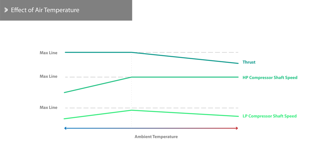
If the fuel control system in place is programmed to maintain a constant pressure ratio (and subsequently thrust), it can only do so up to a certain temperature. Past that point, the fuel flow is automatically adjusted (reduced) to avoid excessive temperatures developing in the turbine which ultimately leads to a drop in thrust.
For an atmospheric temperature of around 45°C and depending on the type of the engine, the drop in thrust due to the climate alone can be up to 20%. In such cases, additional thrust increase systems (such as water injection) might be necessary or very beneficial.
For an atmospheric temperature of around 45°C and depending on the type of the engine, the drop in thrust due to the climate alone can be up to 20%. In such cases, additional thrust increase systems (such as water injection) might be necessary or very beneficial.
Thrust & Power Adjustments
From the above, it has become apparent that external factors can have a significant effect on the deliverable thrust or power of engines of all types. To be able to compare different engines, regardless of the test conditions, we need to express thrust in International Standard Atmosphere (ISA) conditions. For example:
\[T_{adjusted}=T_{stated}\cdot \frac{29.99}{P_0}\]
\[W_{adjusted}=W_{stated}\cdot \frac{29.99}{P_0}\times \sqrt \frac{273+15}{273+t_0}\]
where:
\(P_0\) is the atmospheric pressure in "Hg
\(t_0\) is the atmospheric temperature in °C
\(t_0\) is the atmospheric temperature in °C
8.4 Thrust Distribution
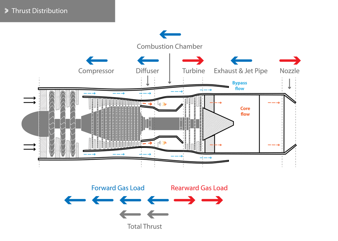
The change in pressure and momentum of the gases inside the jet engines leads to some producing forward thrust and some producing rearward thrust. The rated thrust of the engine is the difference between the two. As the air is compressed it exerts a large forward force and the same is true for the diffuser but to a much smaller magnitude.
As one would expect, the rise in temperature and pressure inside the combustion chamber makes it the single largest contribution towards the forward-acting forces. However, as this mass of air enters the turbine and experiences a drop in pressure, the acceleration of the flow as well as the continuous deflection give rise to a drag force, i.e. a rearward force. Even though some forward forces also develop in the jet pipe of some engine, the exhaust section mostly contributed a rearward force due to the drag at the walls of the propelling nozzle. Broadly speaking, whenever pressure is converted to velocity, rearward forces develop; when velocity is converted to pressure forward forces develop.
As one would expect, the rise in temperature and pressure inside the combustion chamber makes it the single largest contribution towards the forward-acting forces. However, as this mass of air enters the turbine and experiences a drop in pressure, the acceleration of the flow as well as the continuous deflection give rise to a drag force, i.e. a rearward force. Even though some forward forces also develop in the jet pipe of some engine, the exhaust section mostly contributed a rearward force due to the drag at the walls of the propelling nozzle. Broadly speaking, whenever pressure is converted to velocity, rearward forces develop; when velocity is converted to pressure forward forces develop.
Compressor Casing
Generally speaking, to calculate the total thrust for each particular component, we have to calculate it separately at the inlet and outlet conditions. However, for the compressor, we can assume that at the inlet the (gauge) pressure and velocity are zero. For the purposes of this example, we shall ignore the effects and contribution of the bypass stream. It is also given that at the outlet, the compressor has an area of \(A=0.117~\textrm{m}^2\), gauge pressure of \(P=650\cdot 10^3~\textrm{Pa}~(\textrm{N}/\textrm{m}^2)\), velocity of \(V_{c2}=120~\textrm{m/s}\) and a mass flow rate of \(\dot M=70~\textrm{kg/s}\). The thrust can then be calculated using:
\[T=(A\cdot P)+\dot MV_{c2}-0\]
For clarify, let's check the units:
\[\textrm{m}^2\cdot \frac{\textrm{N}}{\textrm{m}^2}+\frac{\textrm{kg}}{\textrm{s}}\cdot \frac{\textrm{m}}{\textrm{s}}\Leftrightarrow \textrm{N}+\frac{\textrm{kg}\cdot \textrm{m}}{\textrm{s}^2}\Leftrightarrow \textrm{N}+\textrm{N}=\textrm{N}\]
Substituting the data:
\[T=(0.117\cdot 650\cdot 10^3)+70\cdot 120-0=84450~\textrm{N}~=84.45~\textrm{kN (Forward)}\]
Diffuser Duct
The conditions at the inlet of the diffuser are the same as the ones at the end of the compressor. The conditions at the end of the diffuser are given to be: area of \(A=0.132~\textrm{m}^2\), gauge pressure of \(P=655\cdot 10^3~\textrm{Pa}\), velocity of \(V_{d2}=112~\textrm{m/s}\) and a mass flow rate of \(\dot M=70~\textrm{kg/s}\). The thrust can then be calculated the same way:
\[T=(A\cdot P)+\dot MV_{d2}-84450 \Leftrightarrow\]
\[T=(0.132\cdot 655\cdot 10^3)+70\cdot 112-84450=\]
\[94300-84450=9850~\textrm{N}~=9.85~\textrm{kN (Forward)}\]
Combustion Chamber
Again, the conditions at the inlet of the combustion chamber are the same as the ones at the end of the diffuser. The conditions at the end of the combustion chamber are given to be: area of \(A=0.375~\textrm{m}^2\), gauge pressure of \(P=640\cdot 10^3~\textrm{Pa}\), velocity of \(V_{ch2}=95~\textrm{m/s}\) and a mass flow rate of \(\dot M=70~\textrm{kg/s}\). The thrust can then be calculated the same way:
\[T=(A\cdot P)+\dot MV_{ch2}-(84450+9850) \Leftrightarrow\]
\[T=(0.375\cdot 640\cdot 10^3)+70\times 95-94300 =\]
\[246650-94300=152350~\textrm{N}~=152.35~\textrm{kN (Forward)}\]
Turbine
The conditions at the end of the turbine are given to be: area of \(A=0.310~\textrm{m}^2\), gauge pressure of \(P=145\cdot 10^3~\textrm{Pa}\), velocity of \(V_{t2}=270~\textrm{m/s}\) and a mass flow rate of \(\dot M=70~\textrm{kg/s}\). The thrust can then be calculated the same way:
\[T=(A\cdot P)+\dot MV_{t2}-(84450+9850+152350) \Leftrightarrow\]
\[T=(0.310\cdot 145\cdot 10^3)+70\cdot 270-246650 =\]
\[63850-246650=-182800~\textrm{N}~=-182.8~\textrm{kN (Rearward)}\]
Exhaust & Jet Pipe
The conditions at the end of the jet pipe are given to be: area of \(A=0.420~\textrm{m}^2\), gauge pressure of \(P=145\cdot 10^3~\textrm{Pa}\), velocity of \(V_{e2}=195~\textrm{m/s}\) and a mass flow rate of \(\dot M=70~\textrm{kg/s}\). The thrust can then be calculated the same way:
\[T=(A\cdot P)+\dot MV_{e2}-(84450+9850+152350-182800) \Leftrightarrow\]
\[T=(0.420\cdot 145\cdot 10^3)+70\cdot 195-63850 =\]
\[74550-63850=10700~\textrm{N}~=10.7~\textrm{kN (Forward)}\]
Nozzle
The conditions at the end of the nozzle are given to be: area of \(A=0.215~\textrm{m}^2\), gauge pressure of \(P=40\cdot 10^3~\textrm{Pa}\), velocity of \(V_{n2}=585~\textrm{m/s}\) and a mass flow rate of \(\dot M=70~\textrm{kg/s}\). The thrust can then be calculated the same way:
\[T=(A\cdot P)+\dot MV_{n2}-(84450+9850+152350-182800+10700) \Leftrightarrow\]
\[T=(0.215\cdot 40\cdot 10^3)+70\cdot 585-74550 =\]
\[49550-74550=-25000~\textrm{N}~=-25.0~\textrm{kN (Rearward)}\]
Summing the above equates to 257.35 kN of forward thrust and 207.80 kN of rearward thrust, yielding a rated thrust of 49.55 kN. Now if we were to consider the engine as a whole and only take the conditions at the end of the nozzle into account (and assume chocked conditions), the thrust calculation for the same conditions would be:
\[T=(P-P_0)\cdot A+\dot MV_{n2}-0 \Leftrightarrow\]
\[T=(40\cdot 10^3-0)\cdot 0.215+70\cdot 585=49550~\textrm{N}~=49.55~\textrm{kN (Forward)}\]
Afterburner
If we now assume that the same engine is fitted with an afterburner, we can recalculate the thrust at the nozzle. The conditions at the end of the nozzle are given to be: area of \(A=0.300~\textrm{m}^2\), gauge pressure of \(P=35\cdot 10^3~\textrm{Pa}\), velocity of \(V_{n2}=730~\textrm{m/s}\) and a mass flow rate of \(\dot M=71~\textrm{kg/s}\). The thrust can then be calculated the same way:
\[T=(A\cdot P)+\dot MV_{n2}-(84450+9850+152350-182800+10700) \Leftrightarrow\]
\[T=(0.300\cdot 35\cdot 10^3)+71\cdot 730-74550 =\]
\[62330-74550=-12220~\textrm{N}~=12.22~\textrm{kN (Rearward)}\]
Which means that the rearward force has been reduced by 12.78 kN and the rated engine thrust has increased to 62.33 kN, an increase of just over 25%!
8.5 Propulsive Efficiency
We have already mentioned that propulsive efficiency takes the following form:
\[\eta_{prop}=\frac{\dot W_t}{\dot W_k}\]
Now, we will modify this expression for three cases. Firstly and for a very simple jet engine, one could assume:
\[\eta_{prop}=\frac{2V}{V_j+V}\]
For a jet engine with a choked exhaust nozzle, this takes the form:
\[\eta_{prop}=\frac{[(P_8-P_0)A+\dot M(V_j-V)]V}{[(P_8-P_0)A+\dot M(V_j-V)]V+\frac{1}{2}\dot M(V_j-V)^2}\]
And finally, we have the most realistic form for a dual flow turbofan where the core flow has properties \(M_1\) and \(V_{j1}\) and the bypass flow has properties \(M_2\) and \(V_{j2}\). We then have:
\[\eta_{prop}=\frac{\dot M_1(V_{j1}-V)V+\dot M_2(V_{j2}-V)V}{\dot M_1(V_{j1}-V)V+\dot M_2(V_{j2}-V)V+\frac{1}{2}\dot M_1(V_{j1}-V)^2+\frac{1}{2}\dot M_2(V_{j2}-V)^2}\]
Aircraft Velocity
If we look at the simplest expression for the propulsive efficiency, it appears that as the aircraft velocity increases, so does the efficiency. For static conditions \(\eta_{prop}=0\) and the maximum value of \(\eta_{prop}=1\) is reached when \(V=V_j\). If we assume that the velocity of the exhaust gases remains constant, then the relationship between the aircraft velocity and the propulsive efficiency is parabolic.
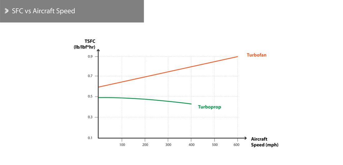
For turboprops, the propulsive efficiency peaks when the aircraft is travelling at around 300-400 mph. In such cases, a further increase in velocity leads to a rapid drop in efficiency. This is because at higher revolutions, the propeller tips can approach sonic speeds, generating shock waves that would significantly affect their operation. On the opposite end, turbojets with low or no bypass are efficient at very high velocities. This disparity effectively drove the development of medium to high-bypass turbofans with 2 or 3 spools that optimise the potential of each shaft as far as the rotational speeds are concerned.
For turboprops, the propulsive efficiency peaks when the aircraft is travelling at around 300-400 mph. In such cases, a further increase in velocity leads to a rapid drop in efficiency. This is because at higher revolutions, the propeller tips can approach sonic speeds, generating shock waves that would significantly affect their operation. On the opposite end, turbojets with low or no bypass are efficient at very high velocities. This disparity effectively drove the development of medium to high-bypass turbofans with 2 or 3 spools that optimise the potential of each shaft as far as the rotational speeds are concerned.
Example
For an aircraft travelling at 600 km/h (324 knots) and a turbojet with exhaust gas velocity of 2000 km/h (555.6 m/s), the propulsive efficiency is:
\[\eta_{prop}=\frac{2\times 600}{600+2000}=0.46 \: \textrm{(46%)}\]
If the speed of the aircraft is increased to 965 km/h (521 knots), the efficiency is then:
\[\eta_{prop}=\frac{2\times 965}{965+2000}=0.65 \: \textrm{(65%)}\]
If the aircraft was equipped with a turboprop instead, the propulsive efficiency would be around 82% when travelling at 600 km/h and 55% when travelling at 965 km/h. A high-bypass turbofan travelling at around 965 mph would have a propulsive efficiency of almost 85%.
Altitude
As the aircraft climbs to higher altitudes, the velocity of the exhaust gases \(V_j\) tends to increase due to the reduction in resistance from atmospheric air. This will normally lead to a reduction in the propulsive efficiency unless the fuel supply system is programmed to maintain a steady \(V_j/V\) ratio.
8.6 Specific Fuel Consumption
Achieving a certain specific fuel consumption and a thrust-to-weight ratio are important design parameters for all jet engines and for civil aerospace in particular. Over the last few decades multiple mechanical, aerodynamic and material developments have led to lighter engines with much improved SFC. The use of increasingly larger bypass ratios and composite materials have also contributed to a reduction in weight and an increase in efficiency.
The specific fuel consumption is directly linked to the thermal and propulsive efficiency of the engine. The thermal efficiency depends on the pressure ratios and the gas temperature at the turbine inlet. Further increasing the turbine temperature is limited by the materials used and, even if that wasn't an issue, the higher temperature would also lead to an increase in the exhaust gas velocity and, thus, a drop in propulsive efficiency. In more modern, high-bypass ratio engines it is possible to achieve both a high thermal and propulsive efficiency by dealing with high exhaust gas temperatures but low to medium exhaust velocities.
Furthermore, the turbines used in turbojets are heavier than those of dual-spool turbofans, as the entirety of the air mass has to flow through the former ones. Similarly, high-bypass engines typically require smaller and lighter compressors and propulsion chambers too. Overall, the cores of high-bypass engines are also shorter than turbojets for the same thrust rating, with the total weight reduction being up to 20%.
Triple-spool engines have an added advantage as the much improved aerodynamic performance enables the reduction of the total number of stages both in the compressor and the turbine.
Aircraft Velocity
As was discussed before, the increase in aircraft velocity leads to an increase in the mass of air going into the engine, which automatically leads to the injection of additional fuel to maintain a healthy air-to-fuel ratio. The relationship between SFC and aircraft velocity is almost linear, as shown below.
From the standard expression for thrust:
From the standard expression for thrust:
\[T=\dot M(V_j-V)\]
It is also true that:
\[\dot M=\dot M_a+\dot M_f\]
The air-to-fuel ratio can be re-arranged and substituted in the thrust equation, such that:
\[\frac{\dot M_a}{\dot M_f}=\mu\]
\[\dot M=(\mu+1)\dot M_f\]
\[T=(\mu+1)\dot M_f(V_j-V)\Leftrightarrow \frac{\dot M_f}{T}=\frac{1}{\mu+1}\cdot \frac{1}{V_j-V}\]
Altitude
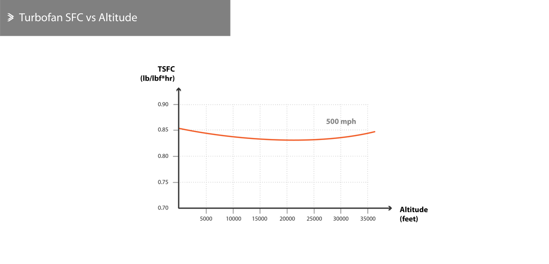
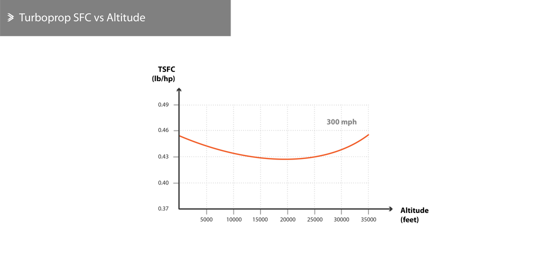
The SFC does not show significant changes over a wide range of altitudes. As the aircraft climbs the SFC drops slightly before picking up again to levels that are marginally higher than sea level ones. This is true for both turbojets/turbofans and for turboprops, even though the variation is slightly higher for the latter.
Back to Aeolus directory |
Next up: 9. Operation |

|